Parameters
WE Parameter level / Range of values
Hysteresis** 5 °C PA4 / 0 to 30 °C
Charging temperature boost*** 10 °C PA4 / 0 to 50 °C
Lag of storage tank charging pump 0.5 PA4 / 0.1 to 10.0
* Parameters serve as limitation of the adjustment range for the DHW temperature to be set
at the rotary switch
** Deactivation value T =
DHW temperature
+
hysteresis
*** Charging temperature T =
DHW temperature
+
charging temperature boost
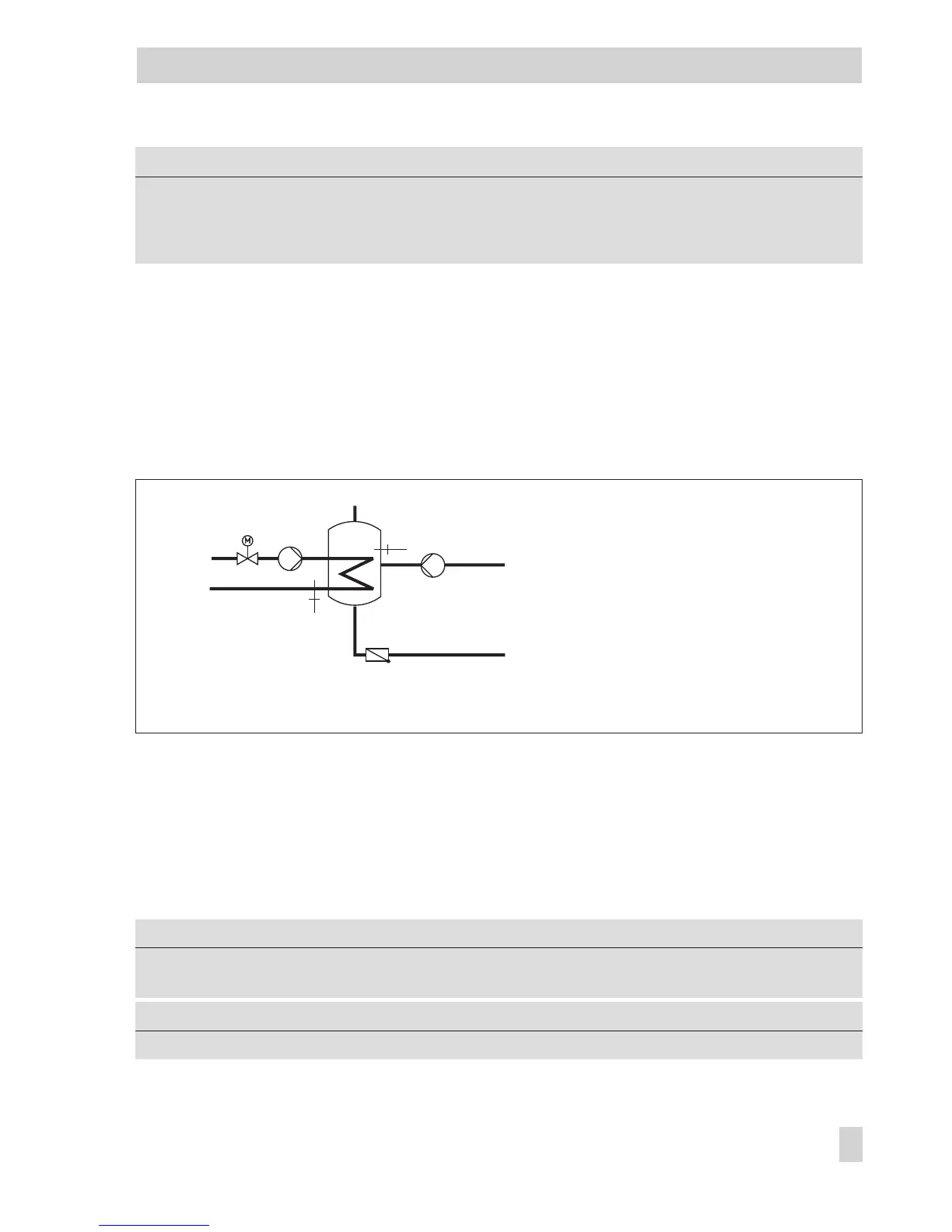
6.1.1 DHW circuit additionally controlled by a globe valve
In systems Anl 7.1, 8.1, 9.1, 9.5, 11.1, 12.1, 13.1 and 21.1, the following version with
globe valve can be configured instead of the three-way valve control in the DHW circuit:
Globe valve and temperature sensor VF2 are used exclusively for return flow temperature
limitation in the schematics shown above. The pre-control circuit provides at least the same
flow temperature as in the standard schematic version which is calculated from
DHW tem-
perature set point
+
Charging temperature boost
+
Boost set point of primary exchanger
control.
The functions and parameters of the DHW heating in the storage tank system are upgraded
by the following settings:
Function WE Configuration
DHW circuit additionally controlled by a
globe valve
0 CO4 -> F20 - 1
Parameter WE Parameter level / Range of values
Maximum return flow temperature 65 °C PA4 / 20 to 90 °C
EB 5579 EN 85
Functions of the DHW circuit
KW
WW
SF1
VF2
ZP
SLP
Rk2/Y2
Fig. 9 · Schematics of a storage tank system with a globe valve for return flow temperature limitation
Rk2/Y2 Control circuit/valve 2
SLP Storage tank charging
pump
SF1 Storage tank sensor 1
VF2 Flow sensor 2
ZP Circulation pump
WW Hot water
KW Cold water