6.2 DHW heating in the storage tank charging system
Start storage tank charging
The controller begins charging the storage tank when the water temperature measured at
sensor SF1 falls below the
DHW temperature set point
by 0.1 °C. If the flow temperature in
the system exceeds the desired charging temperature, the controller tries to reduce the flow
temperature in the heating circuit for up to 3 minutes before the exchanger charging pump is
activated together with the storage tank charging pump.
When there is no heating operation or when the flow temperature in the system is lower, the
exchanger charging pump is switched on immediately. If the temperature currently measured
at sensor SF1 is reached at sensor VF, or after three minutes at the latest, the storage tank
charging pump is switched on.
If a storage tank thermostat is used, the storage tank charging pump is switched on when the
temperature T =
Charging temperature
– 5 °C is reached at sensor VF.
Note: Instead of the
DHW temperature
parameter, the
Charging temperature
can be ad-
justed as the absolute value at the rotary switch if a storage tank thermostat is used.
When the flow sensor VF4 is activated, the set point in the heat exchanger circuit is influ-
enced by the system deviation in the storage tank charging circuit upon activation of the stor-
age tank charging pump: if the temperature measured at flow sensor VF4 is lower than the
desired charging temperature, the set point in the heat exchanger circuit is increased in steps
of 1 °C.
When the set point in the heat exchanger charging circuit reaches the
Max. charging tem-
perature
, the set point is no longer increased. An “Err 4“ error message is generated.
86 EB 5579 EN
Functions of the DHW circuit
WW
SF1
SF2
SLP
TLP
ZP
KW
VF
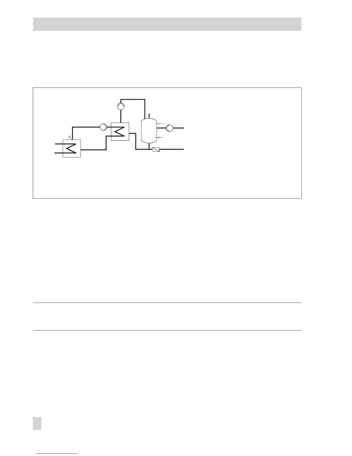
Fig. 10 · Schematics of a storage tank charging system
TLP Exchanger charging pump
VF Flow sensor
SLP Storage tank charging pump
SF1 Storage tank sensor 1
SF2 Storage tank sensor 2
ZP Circulation pump
WW Hot water
KW Cold water