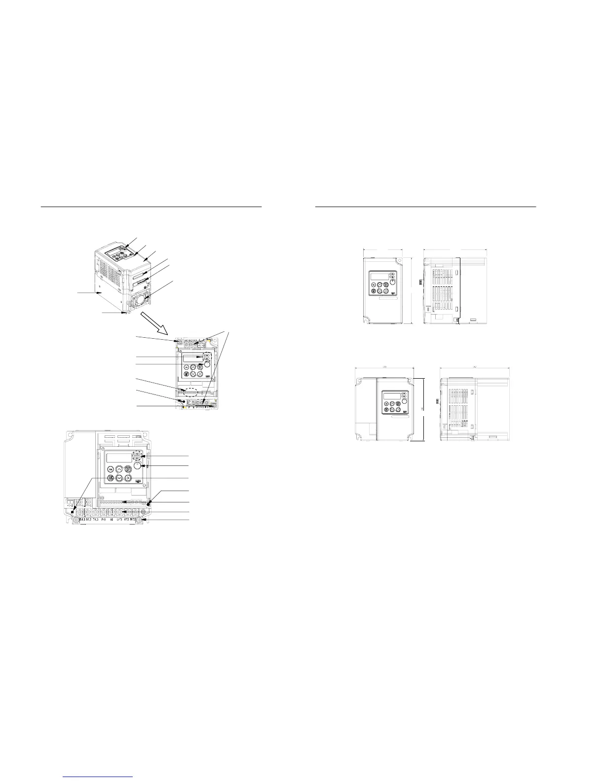
iring holes for control circuit
Ground terminal
Status indicating lamp
Main circuit terminal block
Control circuit terminal block
Digital volume
Ground terminal
Charge lamp
[1 phase 20P4S and 3 phase 20P4, 20P7]
Status indicating lamp
Digital volume
Control circuit terminal block
Main circuit terminal block
Ground terminal
Charge lamp (400V class)
Charge lamp (200V class)
[1 phase 20P7S, 21P5S, 22P2S and
3 phase 21P5, 22P2, 23P7, 40P4~43P7]
Opening the covers
1-6 MOSCON-E7 User’s Manual
1.3 Dimensions
Figure 1.2 Dimensions of 1 phase 20P4 and 3 phase 20P4, 20P7
Figure 1.3 Dimensions of 1 phase 20P7, 21P5 and 3 phase 21P5,
22P2, 40P4~41P5
76 123
128
120 142
128