5. Parameters 5-53
5.7.3.3 Adjusting analog inputs : H2.03, H2.04, H2.06, H2.07
Parameter
No.
Name Unit
Setting
range
Factory
Setting
Changeable
during
operation
H2.03
Voltage Input
Gain
(Terminal 9)
0.1%
0.0
~200.0
100.0 O
H2.04
Voltage Input
Bias
(Terminal 9)
0.1%
-100.0
~100.0
0.0 O
H2.06
Current Input
Gain
(Terminal 10)
0.1%
0.0
~200.0
100.0 O
H2.07
Current Input
Bias
(Terminal 10)
0.1%
-100.0
~100.0
0.0 O
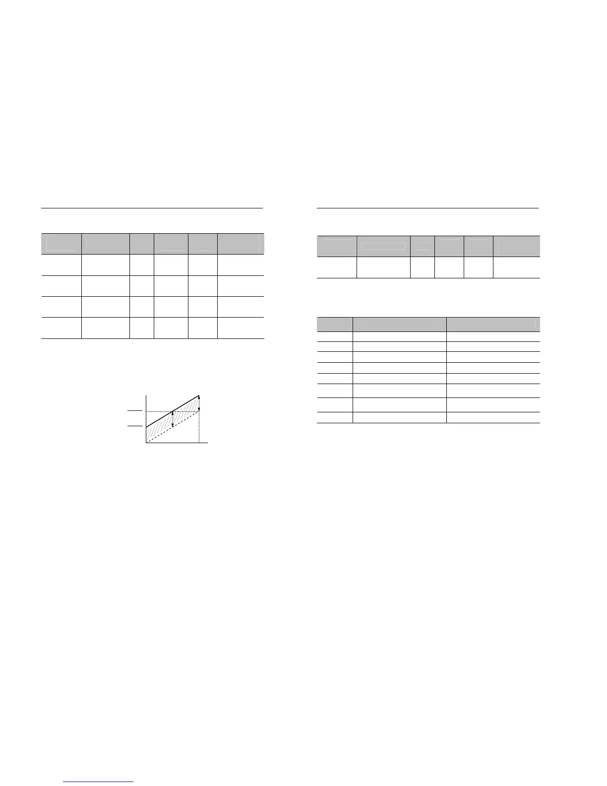
• Adjust gain and bias of analog inputs, as shown in Figure 5.22 if there
are undesirable offset and gain changes in the analog inputs.
• The setting unit of gain and bias changes according to the values in
H2.05. For more details, see the paragraph 5.7.3.4.
Figure 5.22 Gain and Bias
Analog input
Max. Out
hen H2.05=0
Frequency
Command
5-54 MOSCON-E7 User’s Manual
5.7.3.4 Setting the multi-function analog input terminal
function : H2.05
Parameter
No.
Name Unit
Setting
range
Factory
Setting
Changeable
during
operation
H2.05
Function of
Current
Input Terminal
- 0~ 7 0 X
• H2.05 is used to set the function of Ain(no. 10) terminal.
• Constants and function for multi-function analog input
• Setting
Setting
constant
Function Setting unit is the percentage of
0 Frequency command Max. output frequency
1 Frequency gain Max. output frequency
2 Voltage bias Max. output voltage
3 DC breaking current Max. output current
4 Over torque detection level Max. output current
5
Stall prevention level during
operation
Max. output current
6
Minimum frequency command
level
Max. output frequency
7 Jump frequency Max. output frequency