3.Wiring 3-3
• Always turn OFF the input power supply before wiring.
Otherwise, an electric shock or fire may occur.
• Wiring must be performed by a qualified personnel.
• Always check if the volts on the main circuit and control circuit
terminals are properly tightened.
• Be sure to ground the ground terminal.
Otherwise, an electric shock or fire may occur.
• Turn ON the inverter only after completely assembling the covers.
Do not detach the cover when the power is ON.
Otherwise, an electric shock or fire may occur.
• Ground the ground terminal (200V & 400V class: ground to 100
or less). Otherwise, an electric shock or fire may occur.
• Tighten all terminal screws of the main circuit and the control
circuit.
• Check if the voltage of the inverter rated voltage satisfies with the
AC power supply voltage.
Otherwise, it may cause fire or injury.
• Do not perform withstand voltage test on the inverter. It may
damage the semi-conductor element.
• When wiring other devices, read their manuals carefully. Samsung
is not responsible for any accident resulting from user’s carelessness.
If not, it may cause injury or fire.
• Do not connect AC power to output terminal U, V and W.
Otherwise, it may damage the inverter.
• Do not connect electromagnetic switches or contactors to the
output circuits.
DANGER
!
CAUTION
!
3-4 MOSCON-E7 User’s Manual
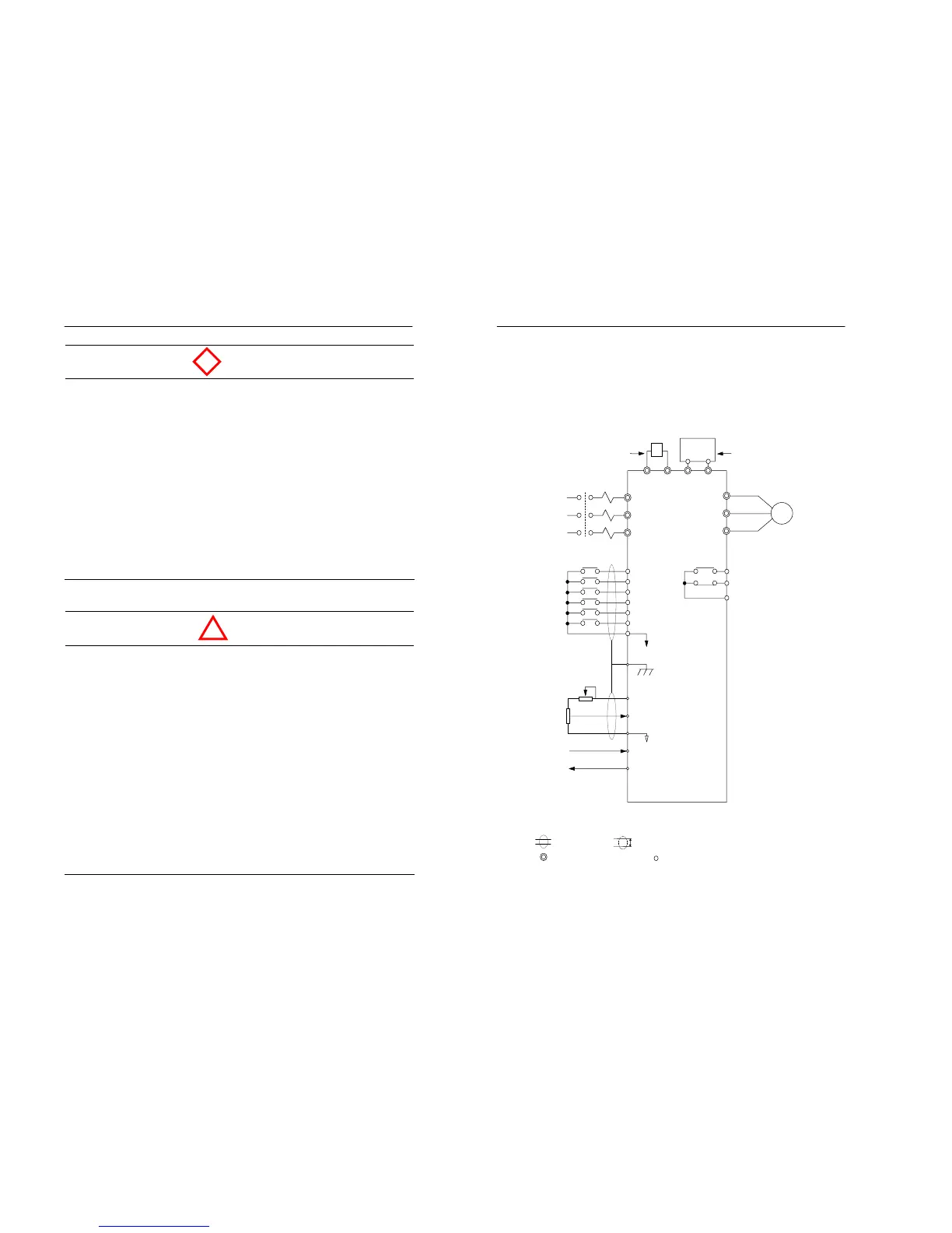
3.1 Connection diagram
The connection diagram of the Moscon-E7 is shown below.
When using the digital operator, the motor can be operated by wiring
only the main circuits.
Figure 3.1 Connection diagram (200V class)
Note 1) : Shield wire, : Twisted pair shield wire.
2) : Main circuit terminal, : Control circuit terminal.
3) Max. current value for +12V voltage of the control circuit terminal No.8 is 20㎃.