3.Wiring 3-21
3
3.9 Cable specification
Determine the cable size for the main circuit. The line voltage drop
should be within 2% of the rated voltage. The line voltage drop is
calculated as below:
Line voltage drop(V) = × cable resistance(/km) × wiring length (m)
× current (A) × 10
-3
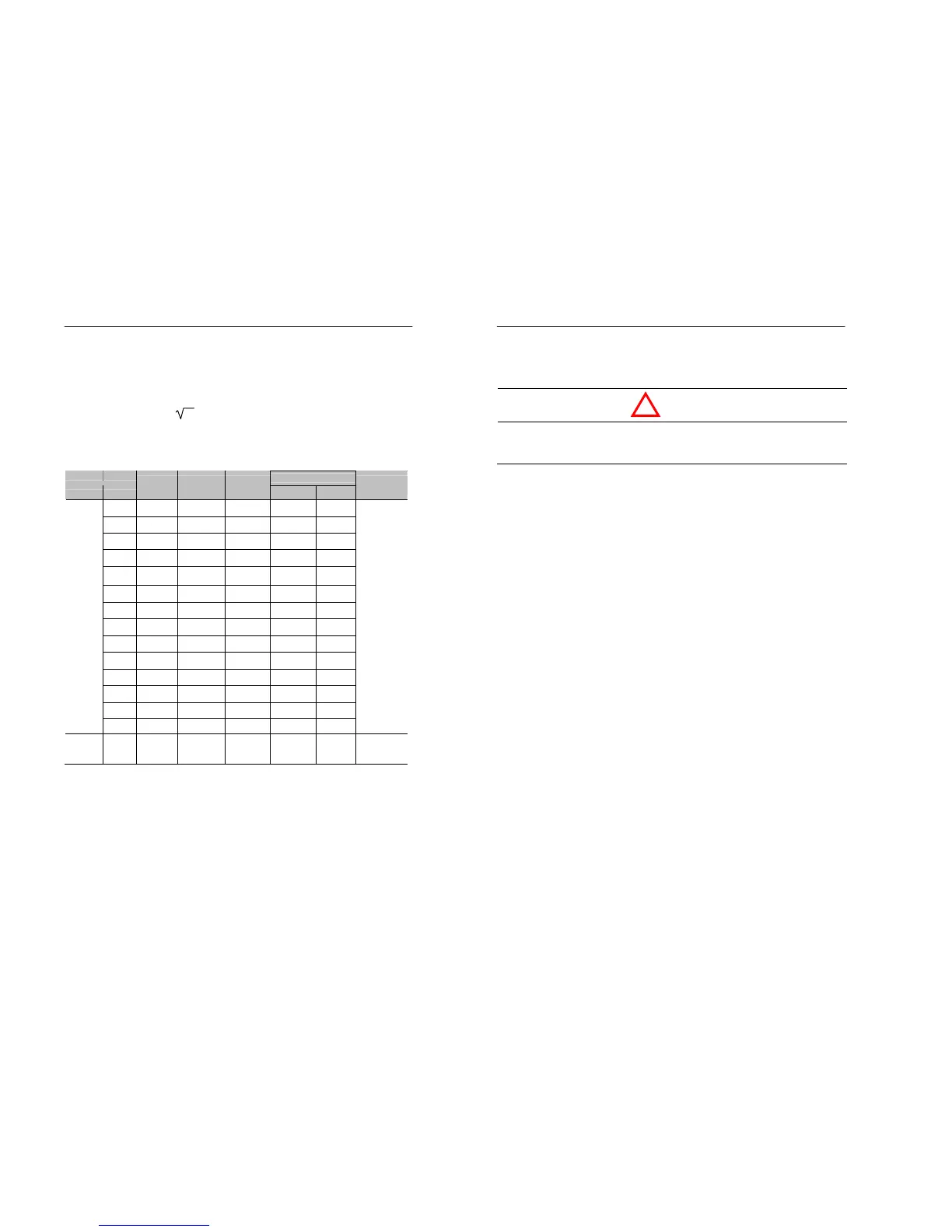
Table 3.9 Cable size
Cable Size
Circuit Model
Ter minal
Screw
ightening
Torque Nm
Crimping
Ter minal
mm
2
AWG
Kind of
Cable
20P4 M3.5 0.8-1.0 2-3.5 2 14
20P7 M3.5 0.8-1.0 2-3.5 2 14
21P5 M4 1.2-1.5 2-4 3.5 12
22P2 M4 1.2-1.5 2-4 3.5 12
23P7 M4 1.2-1.5 5.5-4 5.5 10
20P4S M3.5 0.8-1.0 2-3.5 2 14
20P7S M4 1.2-1.5 2-4 3.5 12
21P5S M4 1.2-1.5 2-4 3.5 12
22P2S M4 1.2-1.5 5.5-4 5.5 10
40P4 M4 1.2-1.5 2-4 2 14
40P7 M4 1.2-1.5 2-4 2 14
41P5 M4 1.2-1.5 2-4 2 14
42P2 M4 1.2-1.5 2-4 2 14
Main
Power
(R/L1,
S/L2,
T/L3,
+1,+2,
P/B,N
U/T1,
V/T2,
W/T3)
43P7 M4 1.2-1.5 2-4 2 14
Power cable
(600V Vinyl-
sheathed wire
or equivalent)
Control All M2 0.22-0.25 - 0.5 ~ 1.25 20-16
Shielded
twisted-pair
Note : The wire size is set for copper wires at 75℃
3-22 MOSCON-E7 User’s Manual
3.10 Wiring check
• After wiring has been complete, check the following. Do not
perform a buzzer check on control circuit.
• Check if all wiring is correct.
Especially check if the power supply is connected the U/T1, V/T2,
W/T3 terminal.
• Check if any wire clippings, screws or other foreign material are left.
• Check if all screws are tight.
• Check if the load status is good.
• Check if any wire ends are contacting other terminals.
CAUTION
!