5. Parameters 5-3
Refer to the following tables and figures to program the inverter for a
specific application.
5.1 Main Feature
MOSCON-E7’s parameters are divided into seven groups and each
group is divided into several subgroups for easier manipulation as
described in Table 5.1.
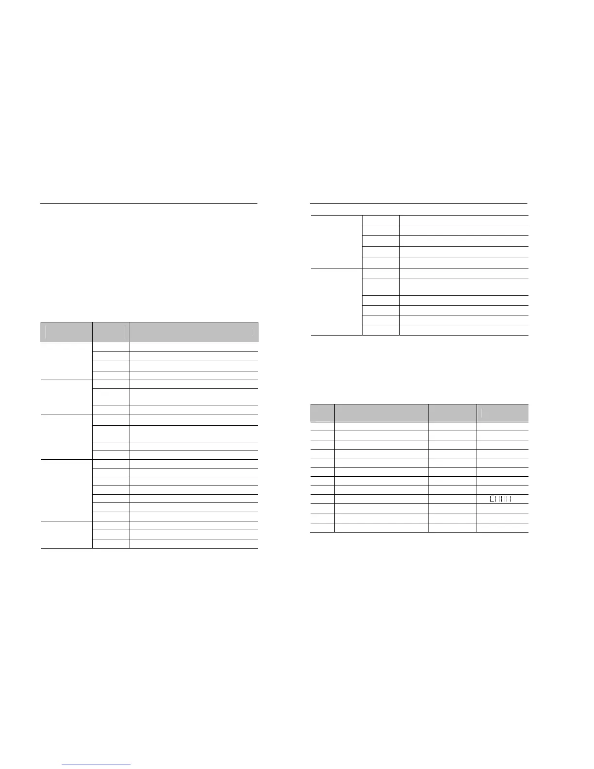
Table 5.1 Functions of each group
Function
(Group)
Parameter
No.
Function
U0 Monitors inverter operational status.
U1 Monitors the inverter status on the last fault.
U2 Monitors the previous faults histories.
Monitoring
(U)
U3 Monitors parameter check lists..
B0 Controls basic settings of the inverter.
B1
Controls the system initialization and password
protection.
Basic Setup
(B)
B2 Sets the capacity of inverter & motor.
F0 Sets the frequency /speed command.
F1
Sets the limit of output frequency. Controls
jump frequency and frequency detection.
F2 Sets the acceleration/deceleration time.
Frequency
Control
(F)
F3 Sets the S-curve accel/decel time.
S0 Controls the DC braking function.
S1 Controls the speed search function.
S2 Controls the Dwell function.
S3 Controls the energy saving operation.
S4 Controls the slip compensation.
S5 Controls the torque compensation.
System
Adjustment
(S)
S6 Controls the system performance.
C0 Selects the V/f pattern.
C1 Controls carrier frequency.
H/W
Functionality
(C)
C2 Sets the parameters of the motor in use.
5-4 MOSCON-E7 User’s Manual
H0 Controls the multi-function contact inputs.
H1 Controls the multi-function contact outputs.
H2 Controls the multi-function analog inputs.
H3 Controls the multi-function analog outputs.
I/O Control
(H)
H4 Controls the settings of digital operator.
P0 Controls the motor protective functions.
P1
Controls the protective functions related to
momentary power failure.
P2 Controls the stall prevention function.
P3 Controls the over-torque etection/protection.
P4 Controls the fault retry.
Protective
Function
(P)
P5 Controls the other protective options.
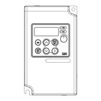
5.1.1 U-Parameter : Monitoring Function
Table 5.2 Operation status
Name Unit Display
U0.01 Effective Command Frequency 0.01Hz xx.xx~xxx.x
U0.02 Current Output Frequency 0.01Hz xx.xx~xxx.x
U0.03 Output Current in RMS 0.01A xx.xA
U0.04 Output Voltage in RMS 1V xxxu
U0.05 DC Link Voltage 1V dxxx
U0.06 Output Power in 0.1kW 0.1kW Pxx.x
U0.07 Motor Speed in RPM 1rpm xxxx
U0.08 Percentage Output Torque 1% oxxx
U0.09 I/O Status bit
U0.10 Cumulative Power On Time 10Hr xxxx
U0.11 Elapsed Time since Power On Min.Sec mm.ss
U0.12 S/W Version r.xxx