3.Wiring 3-5
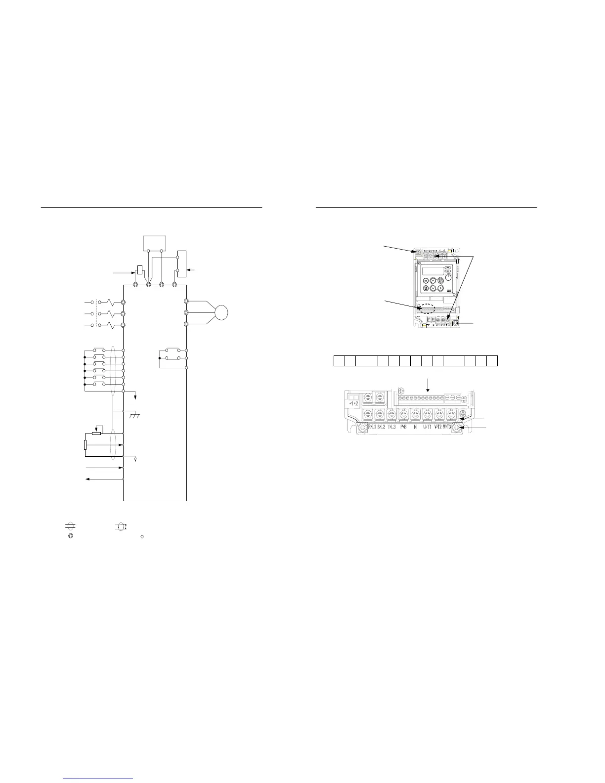
Figure 3.2 Connection diagram (400V class)
Note 1) : Shield wire, : Twisted pair shield wire.
2) : Main circuit terminal, : Control circuit terminal.
3) Max. current value for +12V voltage of the control circuit terminal No.8 is 20㎃.
+1
MCCB
+2
N P/B
Built-in braking unit is available
for the 400V class. Thus, the
external braking resistor can be
installed as an option. External
braking unit is an option
External DC reactor to
improve power factor.
(optional)
Input power
E
8
9
12
10
11
Multi-function
contact input
Multi-function
contact output
DC 30V 1A max
AC 250V 1A max
Braking Unit or Auxiliary Capacitor
(optional)
M
p
3-6 MOSCON-E7 User’s Manual
3.2 Terminal block configuration
1 2 3 4 5 6 7 8 9 10 11 12 A1 B1 C1
[21P5 – 23P7, 40P4 – 43P7]
Figure 3.3 Terminal configuration
Ground terminal
Control circuit
terminal block
Ground terminal
Main circuit terminal
block
[20P4, 20P7]
Control circuit terminal
Main circuit terminal
Ground terminal
[20P4, 20P7]