List of figures - 1
List of figures
1.Overview
Figure 1.1 System diagram -------------------------------------------------------------------- 1-5
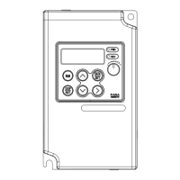
Figure 1.2 Dimensions of 1 phase 20P4 and 3 phase 20P4, 20P7 ------------------------ 1-6
Figure 1.3 Dimensions of 1 phase 20P7, 21P5 and 3 phase 21P5~22P2, 40P4~41P5 -- 1-6
Figure 1.4 Dimensions of 1 phase 22P2 and 3 phase 23P7, 42P2~43P7 --------------------1-7
2. Installation
Figure 2.1 Example of nameplate ---------------------------------------------------------- 2-3
Figure 2.2 Installation space ------------------------------------------------------------------- 2-8
3. Wiring
Figure 3.1 Connection diagram (200V class) ----------------------------------------- 3-4
Figure 3.2 Connection diagram (400V class) ------------------------------------------- 3-5
Figure 3.3 Terminal configuration ------------------------------------------------------- 3-6
Figure 3.4 Peripheral devices ------------------------------------------------------------- 3-9
Figure 3.5 Reactor installation ---------------------------------------------------------- 3-11
Figure 3.6 Power supply noise filter installation ------------------------------------- 3-14
Figure 3.7 Noise filter on the output side --------------------------------------------- 3-15
Figure 3.8 Dealing with inductive noise ------------------------------------------------- 3-16
Figure 3.9 Dealing with radio interference ----------------------------------------------- 3-16
Figure 3.10 Ends of twisted-pair cables ------------------------------------------------- 3-18
Figure 3.11 Direction of motor’s rotation ------------------------------------------- 3-18
Figure 3.12 Multiple grounding ---------------------------------------------------------- 3-20
4. Digital operator
Figure 4.1 Monitoring functions of digital operator ---------------------------------- 4-5
Figure 4.2 Test run using digital operator ---------------------------------------------- 4-7
5. Parameters
Figure 5.1 Parameter setting method --------------------------------------------------------- 5-7
Figure 5.2 Selecting monitoring group (U) --------------------------------------------------- 5-8
Figure 5.3 Timing chart for multi-step and JOG operation --------------------------- 5-15
Figure 5.4 Upper and lower limits of the frequency reference ------------------------ 5-16
2 - MOSCON-E7 User’s Manual
Figure 5.5 Setting jumping frequencies -------------------------------------------------- 5-18
Figure 5.6 Acceleration/deceleration time switching frequency --------------------- 5-19
Figure 5.7 Setting S-curve characteristics ---------------------------------------------- 5-21
Figure 5.8 DC braking timing chart -------------------------------------------------------- 5-22
Figure 5.9 Speed search timing chart -------------------------------------------------------- 5-24
Figure 5.10 Timing chart for dwell function -------------------------------------------- 5-25
Figure 5.11 Slip compensation limit -------------------------------------------------------- 5-28
Figure 5.12.1 V/f pattern : settings 0~14 & setting15 -------------------------------- 5-33
Figure 5.12.2 V/f pattern : settings 0~14 & setting15 ---------------------------------- 5-34
Figure 5.13.1 V/f pattern : settings 0~14 & setting15 ---------------------------------- 5-35
Figure 5.13.2 V/f pattern : settings 0~14 & setting15 ----------------------------------- 5-36
Figure 5.14 User-defined V/f pattern ------------------------------------------------------- 5-37
Figure 5.15 3-wire sequence wiring example ------------------------------------------------ 5-43
Figure 5.16 Time chart for 3-wire sequence ----------------------------------------------- 5-43
Figure 5.17 Using two accel/decel time ------------------------------------------------------ 5-45
Figure 5.18 Acceleration/deceleration jamp hold -------------------------------------------- 5-46
Figure 5.19 Timing chart for up and down commands ------------------------------------- 5-47
Figure 5.20 Timing chart for DC injection braking command ------------------------------- 5-48
Figure 5.21 Timing chart for the external search command ------------------------------- 5-49
Figure 5.22 Gain and bias ------------------------------------------------------------------------- 5-53
Figure 5.23 Monitor output adjustments ----------------------------------------------------- 5-56
Figure 5.24 Motor protection operating time ------------------------------------------------- 5-61
Figure 5.25 Acceleration stall prevention function : P2.01=1 ----------------------------- 5-66
Figure 5.26 Stall prevention limit during acceleration ---------------------------------------- 5-66
Figure 5.27 Deceleration stall prevention function : P2.04=1 ------------------------------ 5-67
Figure 5.28 Run stall prevention function : P3.05=1 or 2 ------------------------------------- 5-69
Figure 5.29 Timing chart for overtorque detection ------------------------------------------- 5-71