-11
Stall Prevention
Name Unit
Setting
Range
Factory
Setting
Changeable
During Operation
Page
P2.01
Stall Prevention
at Start
- 0~1 1 X 5-65
P2.02
Stall Prevention
Level at Start
1% 0~200 170 ○ 5-65
P2.03
Stall Prevention
at Acc Limit
1% 0~100 50 ○ 5-66
P2.04
Stall Prevention
at Stop
- 0~1 1 X 5-67
P2.05
Stall Prevention
in Running
- 0~2 1 X 5-68
P2.06
Stall Prevention
Level in Running
1% 0~200 170 ○ 5-68
Over Torque Detection
Name Unit
Setting
Range
Factory
Setting
Changeable
During Operation
Page
P3.01
Overtorque
Detection
- 0~4 0 X 5-70
P3.02
Overtorque
Detection Level
1% 0~300 180 ○ 5-71
P3.03
Overtorque
Delay Time
1sec 0.0~10.0 0.1 X 5-71
Retry Fault
Name Unit
Setting
Range
Factory
Setting
Changeable
During Operation
Page
P4.01
Number of
Fault Retry
- 0~10 0 X 5-72
P4.02
Output Terminal
Function at Retry
- 0~1 0 X 5-73
Fan Error
Name Unit
Setting
Range
Factory
Setting
Changeable
During Operation
Page
P5.01 Fan Error - 0~1 0 X 5-73
A-12 MOSCON-E7 User’s Manual
Appendix C
E7 Dynamic Brake User’s Manual
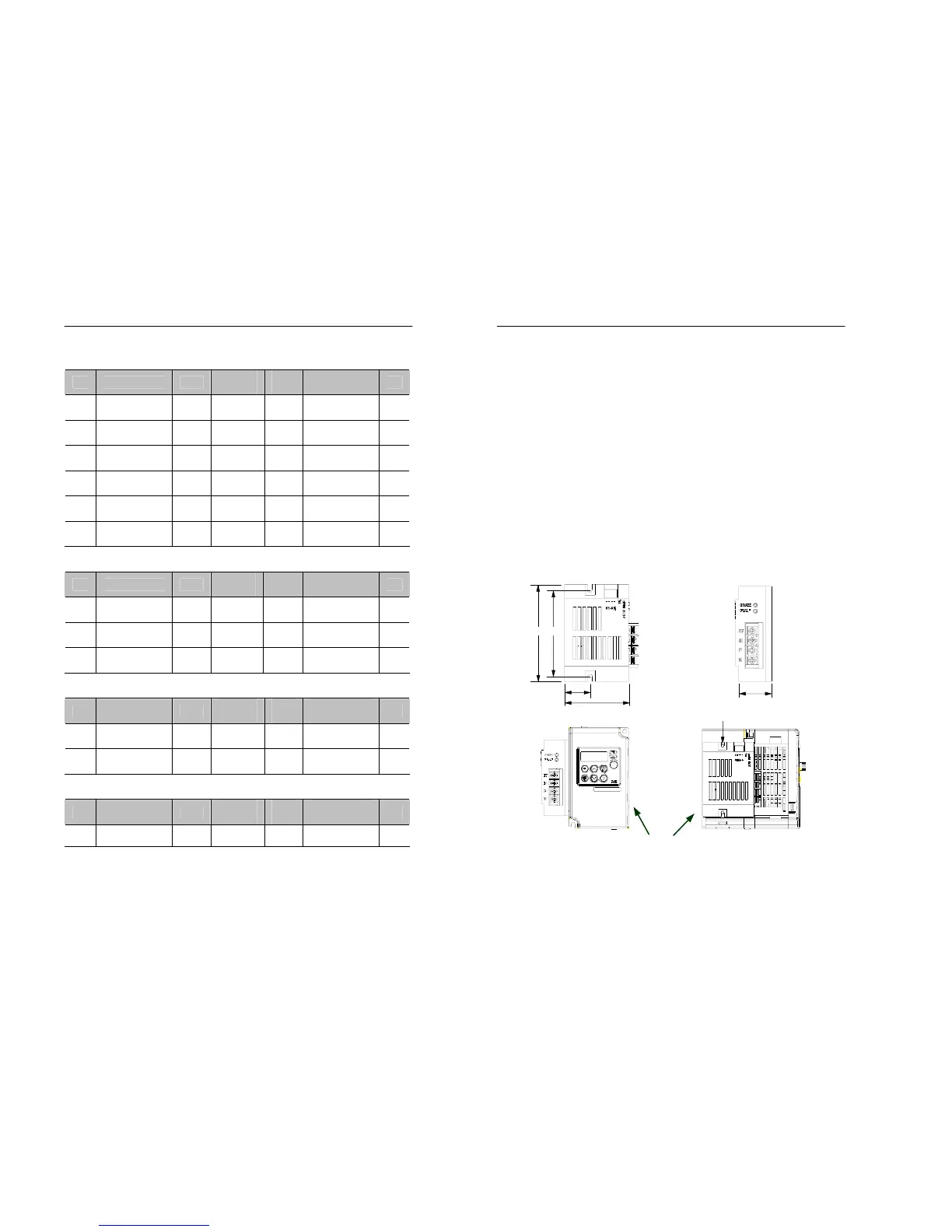
1. Mounting
For the optimal performance of the dynamic brake, mount it in a place,
which satisfies the conditions listed below.
- Refer to the figure 1 for the dimensions and installation space.
- A dynamic brake and braking resistor generate heat, thus install the
peripheral devices, which are not tolerant to heat, far away from
them.
- Refer to the figure 1 for the mounting method.
Dynamic Brake
MOSCON-E7
Figure 1. Mounting method
M4 SCREW