OfficeServ 7400 INSTALLATION
TECHNICAL MANUAL PART 7 MAY 2010
7.8
connection to one telephone. Connecting multiple telephones to a port may result in
incorrect operation or damage to the card. See Figure 7.10.
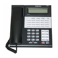
iDCS KDB-SINGLE LINE INTERFACE (FKDBS)
This is a daughterboard that can be installed only in the 18 or 28 button keyset. The FKDBS
will provide one additional SLI circuit for the connection of any standard telephone device.
This FKDBS will only operate when the keyset is connected to an 8 port DLI card it can use the
second B channel. Each port on this card is intended for connection to one telephone.
Connecting multiple telephones to a port may result in incorrect operation or damage to the
card. See Figure 7.9.
NOTE: The circuitry on a FKDBS does not provide a loop open disconnect signal nor
have the over-voltage protection necessary for OPX operation.
iDCS KDB-FULL DUPLEX (FKDBF)
The standard speakerphone mode of operation for an iDCS keyset is “half duplex”. This means
that you cannot transmit and receive speech at the same time. Adding a FKDBF to your keyset
will convert the speakerphone into full duplex mode enhancing its operation. In addition, the
FKDBF may have up to 3 external microphones attached to it for conference room type
applications. These microphones require an “EXTMIC” key programmed on the keyset to
activate or deactivate them. See Figure 7.9.
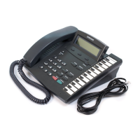
DS KDB-FULL DUPLEX (KDBF)
This is a daughterboard that can only be installed in the 21D or 14D button keysets. The
standard speakerphone mode of operation for a DS keyset is “half duplex”. This means that
you cannot transmit and receive speech at the same time. Adding a KDBF to your keyset will
convert the speakerphone into full duplex mode enhancing its operation. In addition, the
KDBF may have up to 3 external microphones attached to it for conference room type
applications. These microphones require an “EXTMIC” key programmed on the keyset to
activate or deactivate them. See Figure 7.10.
KDB-DLI
This daughterboard can be installed only in the DCS 12 or DCS 24 button keyset. Before
performing this procedure, unplug the line cord from the keyset and remove the base wedge.
Place the keyset face down on a soft surface and remove the four base retaining screws (see
Figure 7.10). Separate the base from the keyset and place the keyset aside. Attach the KDB-DLI to
the keyset base with the four screws that are supplied (see Figure 7.11). Take care to ensure that
the modular socket shows through the access hole in the base (see Figure 7.12).
Invert the
base assembly over the keyset and plug the ribbon cable into the socket on the keyset PCB
(see Figure 7.13)
while making sure that no damage occurs to the keyset PCB. Reattach the
base to the keyset and test to ensure normal keyset operation.