OfficeServ 7400 INSTALLATION
TECHNICAL MANUAL PART 3 MAY 2010
3.41
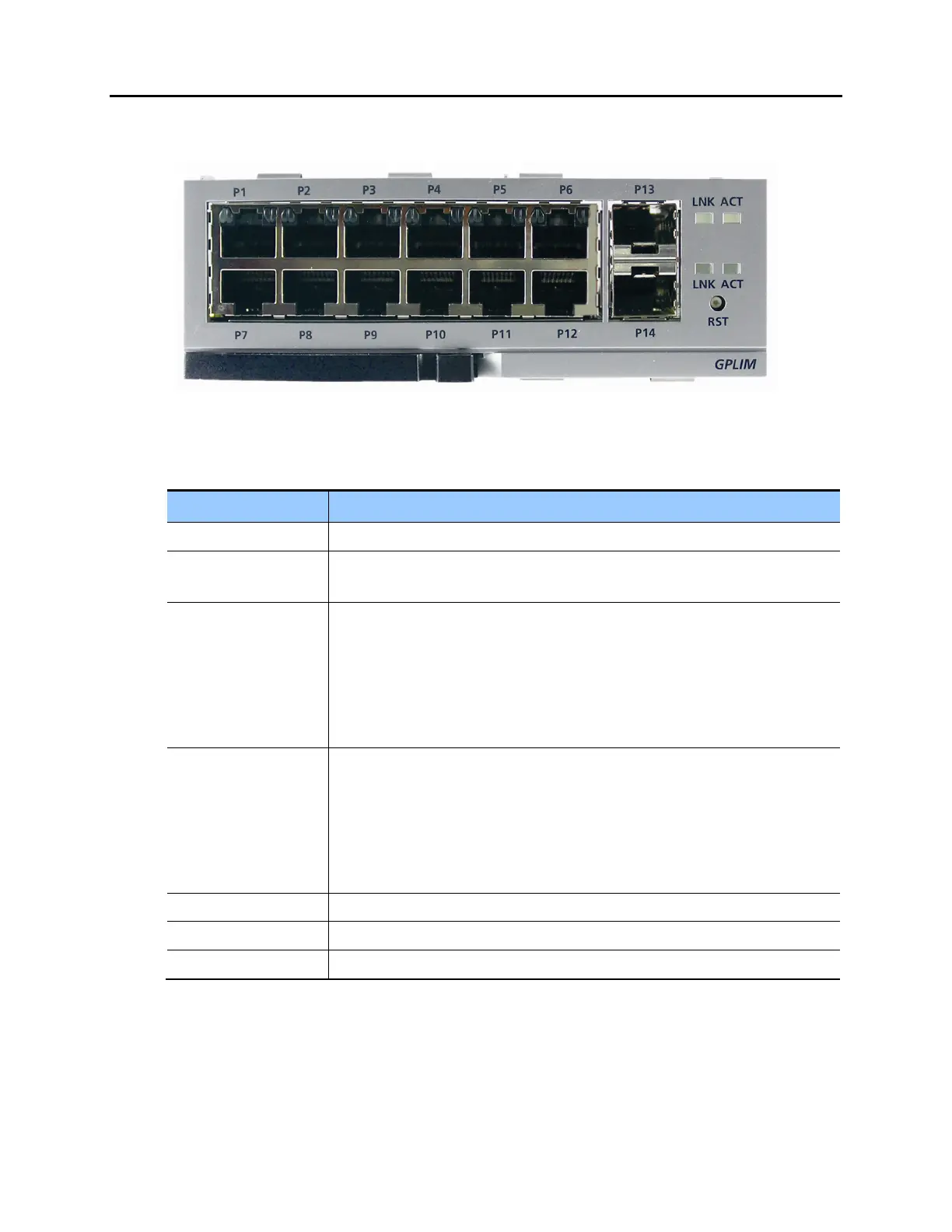
FRONT VIEW OF GPLIM MODULE
Figure 3.42 Front View of the GPLIM
Table 3.18 Ports and LEDs of GPLIM
Ports & LEDs Function Description
P1~P12 Ports for connecting to 10/100 Base-T Ethernet.
P13, P14 Ports for connecting to 1000 Base-SX/LX/TX Gigabit Ethernet (GbE). Requires
SFP connector.
Left LEDs of P1~P6 First LED: Link operation of P1~P6
- On: LED turns green when a link is in operation
- Blink: Each port blinks on active status
Second LED: 10/100 Base-T operation of P1~P6
- Off: Operated in 10 Base-T
- On: Operated in 100 Base-TX
Right LEDs of P1~P6 First LED: Link operation of P7~P12
- On: LED turns green when a link is in operation
- Blink: Each port blinks on active status
Second LED: 10/100 Base-T operation of P7~P12
- Off: Operated in 10 Base-T
- On: Operated in 100 Base-TX
LINK LED turns on when P13~P14, which are Giga ports, is connected
ACT LED blinks when P13~P14, which are Giga ports, is on active status
RST Button for resetting GPLIM