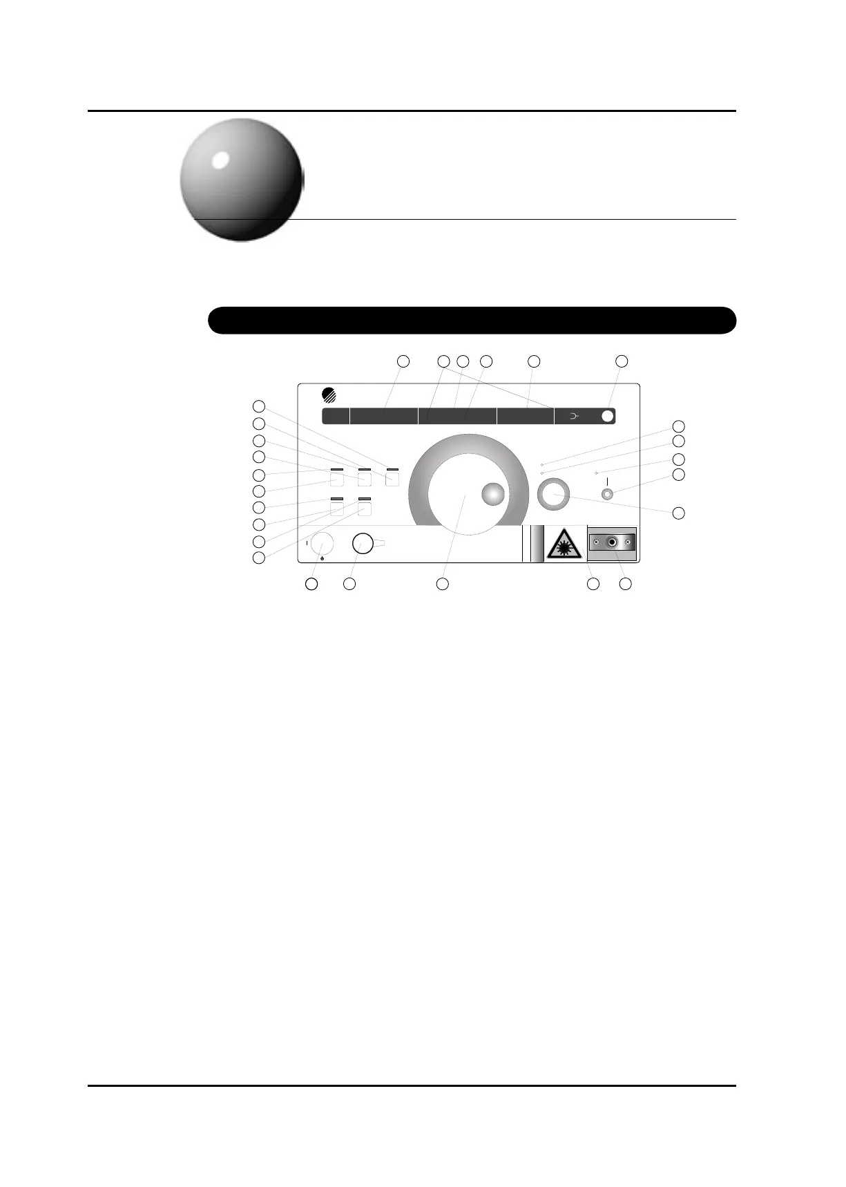
(1) Wavelength / ne tuning display panel
This displays the currently set wavelength and the wavelength at wavelength calibration. When
ne tuning is turned ON, it displays the currently set control amount.
(2) Temperature stabilization (TEMP. ERROR)
This LED indicates that temperature control is not stable. Use the system after
“TEMP.ERROR” display goes off. For several minutes after turning the system on, the display
is on. The display goes out after about 10 minutes, which varies with external environment.
This is same when target temperature is set by communication command.
(3) Current Limit (CURR. LIMIT)
This LED indicates that the injection current reaches its hardware limit owing to the fact that
too large a target was set with the Automatic Power Control (APC). It is not possible to have
the same optical output across 100% of the tuning range. The gain is tailing off at both ends of
the tuning range, especially the short wave side. Refer to the test records.
(4) Optical output power display panel / GP-IB address display panel
1. This displays optical output power. The minimum display value of optical output power is
-40.00dB/0mW
2. When changing GP-IB address, it displays GP-IB address.
(5) Unit display
The unit lit shows the unit of data on the current display panel.
(6) Optical output power unit change key / Wavelength calibration key
This toggles the unit of optical output power by dBm or mW.
Pressing this key while the SHIFT LED is lit causes wavelength calibration.
Artisan Technology Group - Quality Instrumentation ... Guaranteed | (888) 88-SOURCE | www.artisantg.com
 Loading...