TUNABLE LD LIGHT SOURCE TSL-210
4-1
4
Principle of Operation
Grating
LD
L 2
L 1
•Rotating table
•Direct operating
table*
ISO
L 3
CPU Control
• Temperature control
• Current control
• Diffraction grating angle control
• Others
GP-IB
PD
RS-232C
Mirror
SPC Connector
ATT
AIF
SIF
Temperature controlled chamber
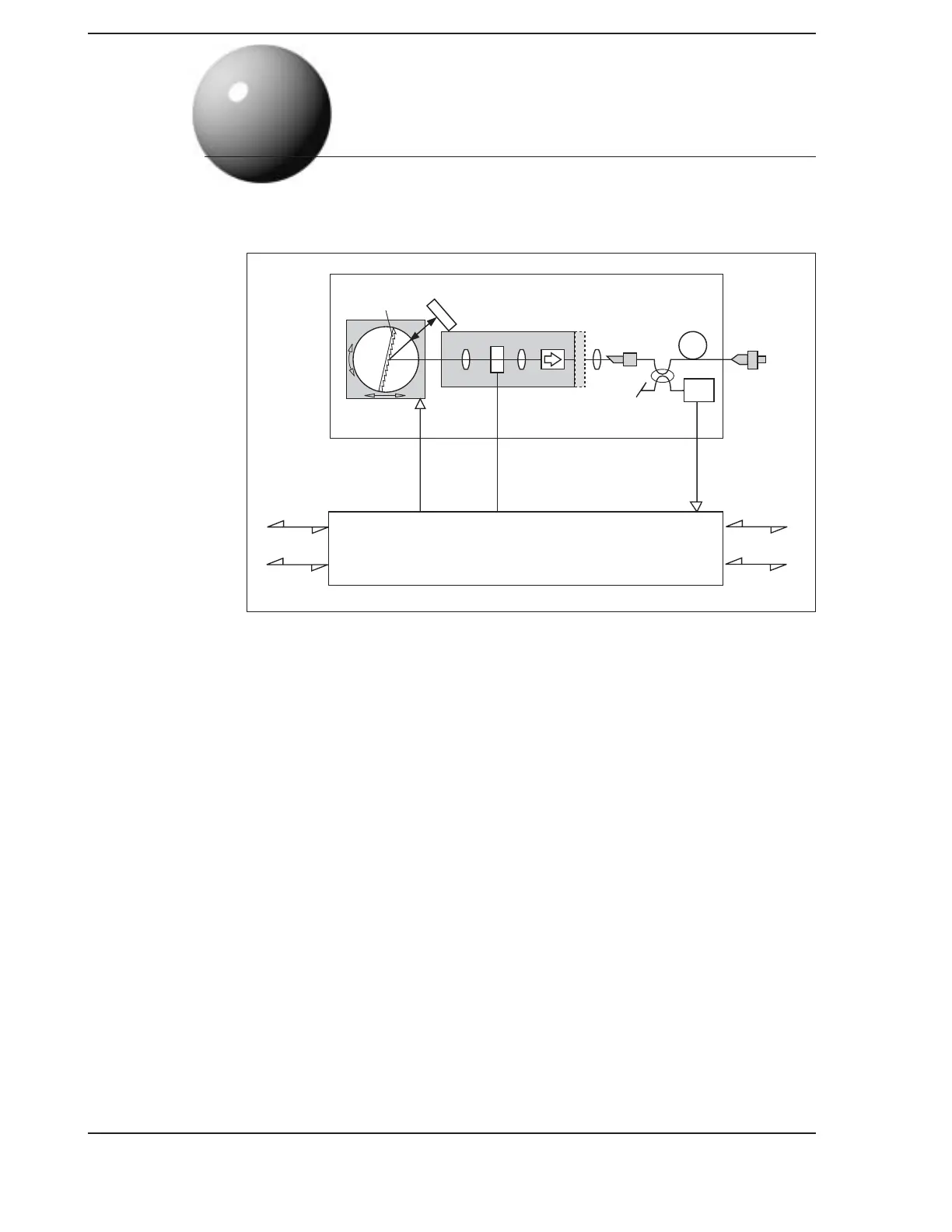
FIG.1 Structure diagram of TSL-210
The structure of the TSL-210 is shown in FIG 1. The basic design is a Fabry-Perot type where the
semiconductor laser (LD) has one end Anti-Reflection (AR) coated. Within the LD chamber, the
LD, a lens in cavity and an output lens (to make up the external cavity), while an isolator prevents
light from re-entering the chamber. Temperature control of the chamber is accomplished via a
Peltier device. As shown in FIG 1, the light emitted from the AR coated surface of the LD is
collimated by the lens. The wavelength is then selected by the diffraction grating; the light is then
reflected by mirror back through the diffraction grating where the wavelength is selected again,
and then the wavelength component dissipated at the same angle as the incident angle is
combined from the AR coated surface of the LD by the lens again. With current injected into the
LD, if the return light from the diffraction grating and the gain inside of the LD are sufficient,
laser oscillation will be carried out by the external cavity structure. The use of diffraction grating
as a reflecting mirror to configure the external cavity structure enables oscillation in single
vertical mode; high-precision control of the diffraction grating allows for tuning of the oscillated
wavelength.
The output light from the external cavity semiconductor laser passes through a two-stage isolator
that limits return light due to back-reflection to less than - 60 dB. The output light then passes
through a variable optical attenuator and is input into the optical fiber. To limit the interference
within the fiber caused by end reflections, the end of the fiber is obliquely polished and an SPC-
type output connector is used. (APC is available as an option). The optical power is also
monitored through a separate optical fiber coupler to compensate for wavelength sensitivity.
Artisan Technology Group - Quality Instrumentation ... Guaranteed | (888) 88-SOURCE | www.artisantg.com
 Loading...