Chapter 5 Configuring the PM135 Configuring Communication Protocols
110 PM135 Powermeter Series
5.6 Configuring Communication Protocols
This section describes how to customize protocol options for use with your
application software.
Configuring Modbus
Modbus Point Mapping
The PM135 provides 120 user assignable registers at addresses 0 to 119.
You can re-map any register available in the meter to any assignable
register so that registers found at different locations may be accessed
with a single request by re-mapping them to adjacent addresses.
Initially these registers are reserved and none of them points to an actual
data register. To build your Modbus register map:
1. Select Protocol Setup from the
Meter Setup menu, and click on
the Modbus Registers tab.
2. Click on the Default button to cause
the assignable registers to reference
the actual default meter register
6656 (0 through 119 are not
allowable register addresses for re-
mapping).
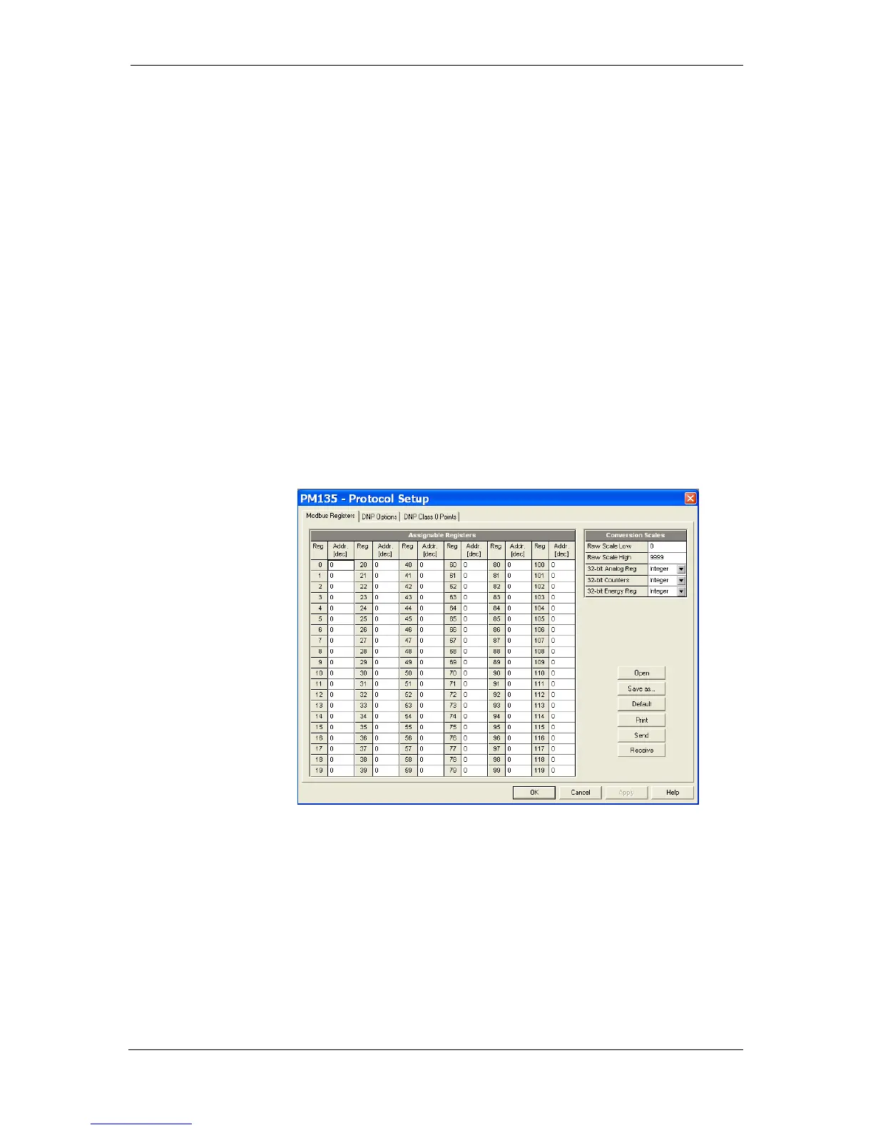
Figure 5-21: Protocol Setup Dialog Box – Modbus Registers Tab
3. Type in the actual addresses you
want to read from or write to via the
assignable registers. Refer to the
PM135 Modbus Reference Guide for
a list of the available registers. Note
that 32-bit Modbus registers should
always start at an even register
address.
4. Click Send to download your setup
to the meter.