The equipment installation shall conform to the following
instructions:
a) a switch or circuit-breaker shall be included in the building
installation;
b) It shall be in close proximity to the equipment and within
easy reach of the OPERATOR;
c) It shall be marked as the disconnecting device for the
equipment.
Before installing, ensure that all incoming power sources
are shut OFF. Failure to observe this practice can result in
serious or even fatal injury and damage to equipment.
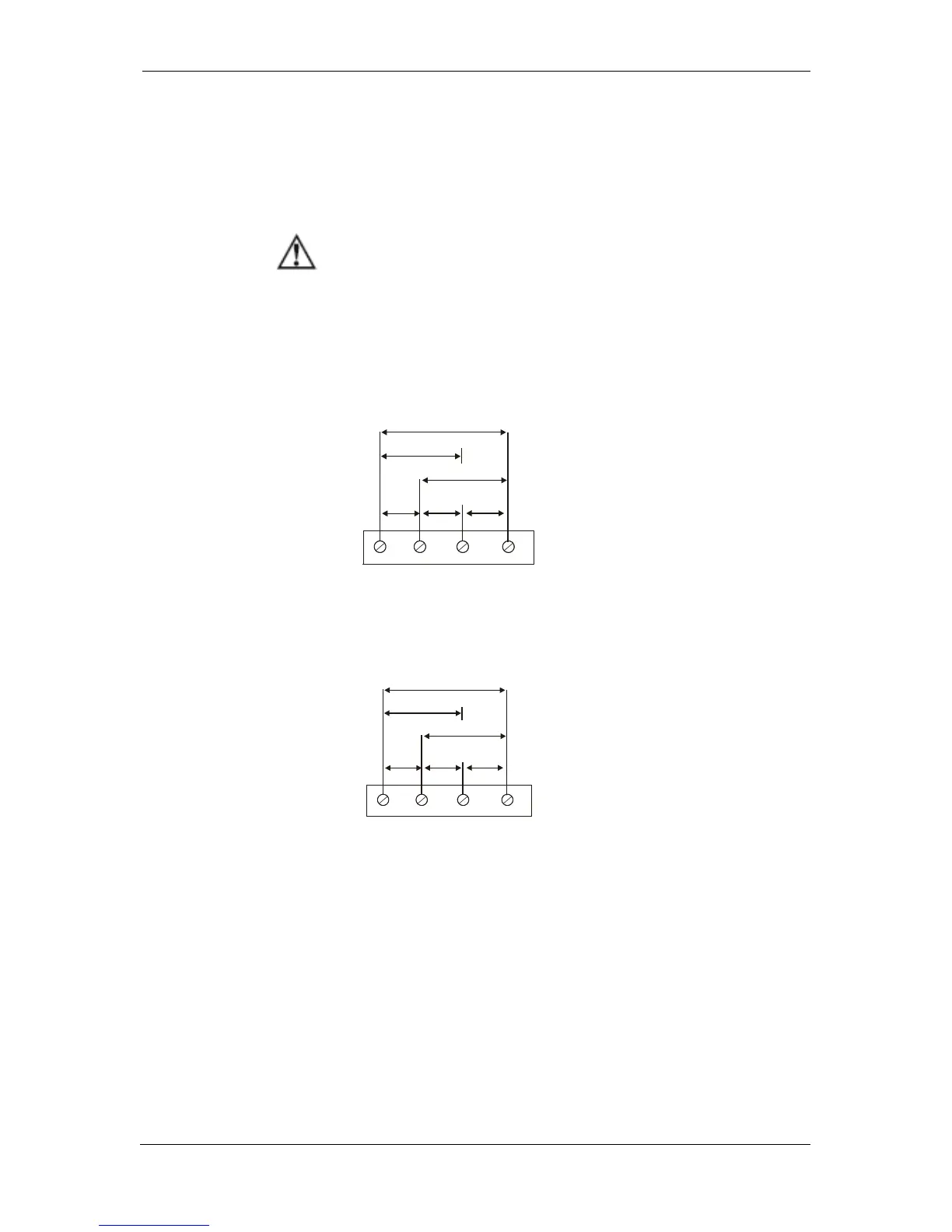
690V Inputs (Standard)
690V inputs are usually used with direct connection. Use any of the seven
wiring configurations shown in Figures 2-8 through 2-15.
120V Inputs (Option U)
120V inputs usually imply use of a potential transformer (PT). The PT
requires use of any of the four wiring configurations shown in Figures 2-7
through 2-10.
Current Input Connection
The PM135 series provide two different CT connections:
Using internal CT, the PM135 does not have current terminals
Using external CT (HACS – High Accuracy SATEC Current Sensor),
the PM135 provides current terminals
To connect to the external CT, pass the external CT wire through the
meter CT core, see Figure 2-8 for details and observe the arrow that
indicates the current direction.