Chapter 2 Installation Electrical Installation
PM135 Powermeter Series 25
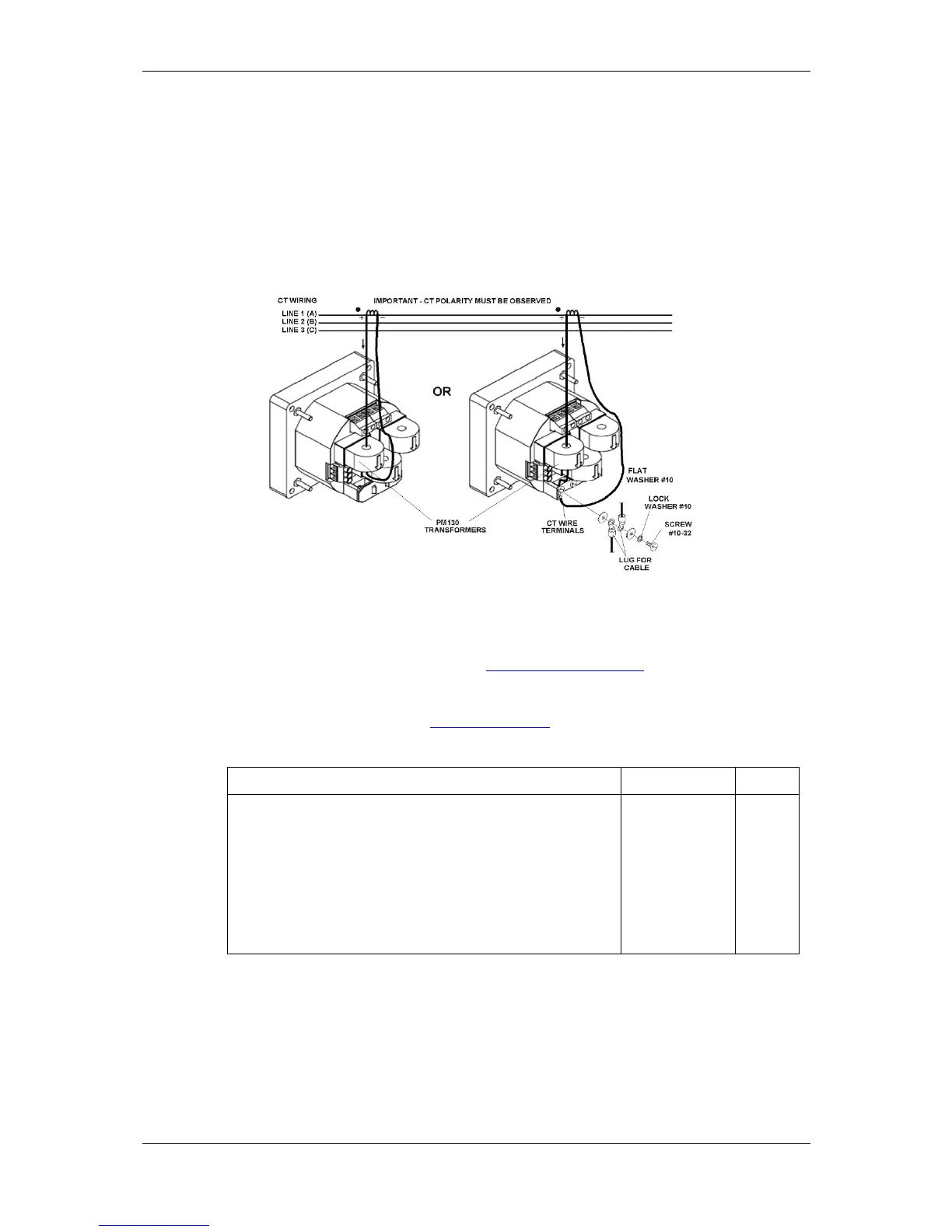
In case of a retrofit application where each external CT ends with two
wires:
1. Pass one wire through the meter CT
core.
2. Connect the wire to one of the
meter termination screws.
3. Connect the second wire from the
external CT to the termination screw
to close the loop.
Figure 2-8. Current Input Connection
Wiring Diagrams
For AC input ratings, see Technical Specifications in Appendix A for more
details.
Table 2 presents the available wiring configurations in the meter. For
more details, see Basic Meter Setup in Chapter 5.
Table 2: Wiring Configurations
 Loading...


