Electrical Connection
The remote display is connected to the meter via a 3-wire or
5-wire communication cable provided with two 15-pin D-type
connectors.
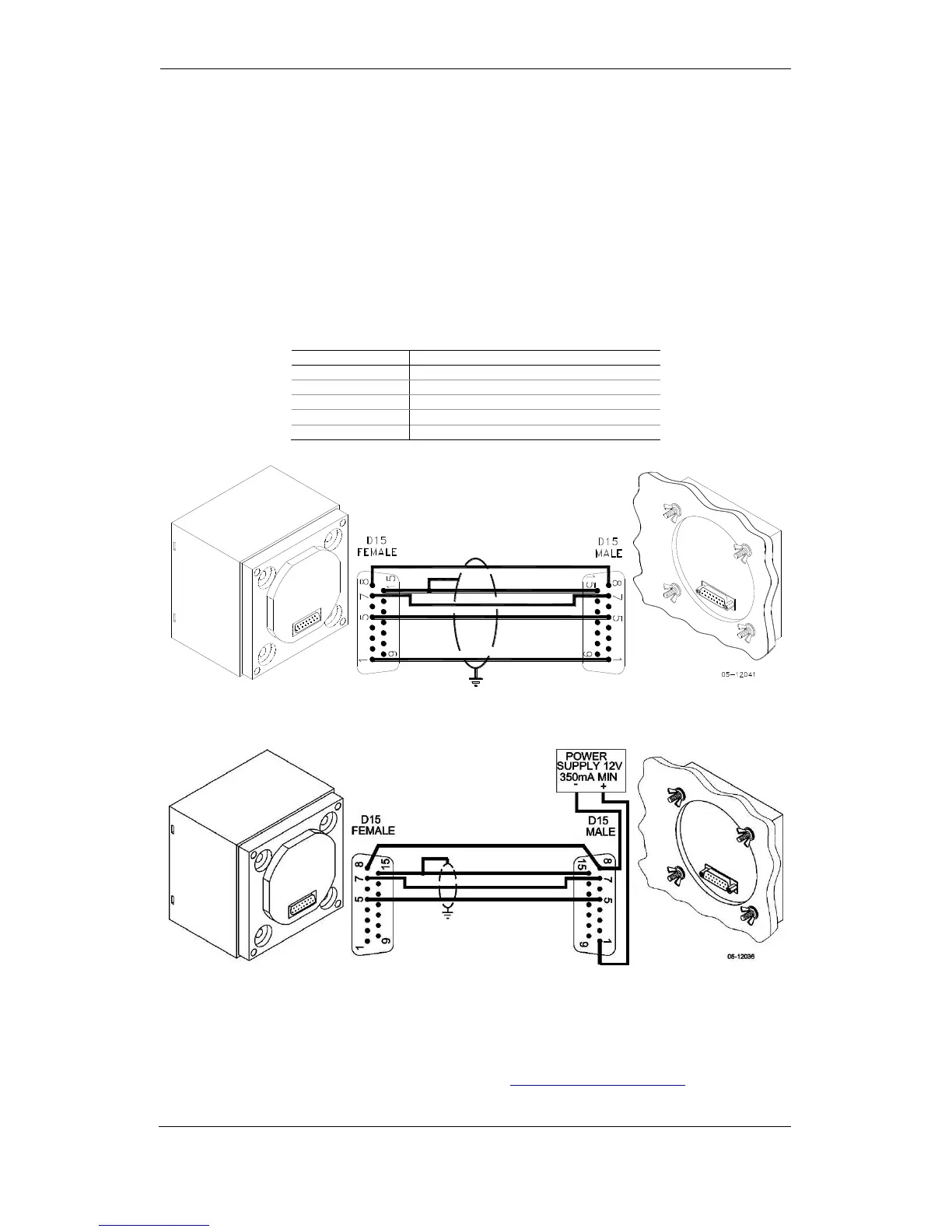
At distances of up to 100 m, the display receives power
through the communication cable directly from the meter.
Connect pins 1 and 8 on both sides as shown in Figure 2-13.
At distances above 100 m, supply power from a separate 12V
DC power source (a 12V AC/DC adapter can be used).
Connect the positive wire to pin 1 and the negative wire to pin
8 as shown in Figure 2-14.
Figure 2-13 Self-powered remote display connection
Figure 2-14 Remote display powered from a 12V DC power source
If required, the remote display may be connected to one of the
regular meter ports COM1 or COM2 via a three-wire RS-485
communication cable using a separate 12V DC power source
as shown in Figure 2-14. See Communications Connections
for connector pin-outs and connection diagrams. The meter