Chapter 3 Display Operations
Indicators and Controls
Display Diagnostics
The display may indicate a connection error as shown on the
left picture if it fails to establish a connection with the meter.
Check the connection between the display module and the
meter body. If the error message is still displayed, contact your
local distributor.
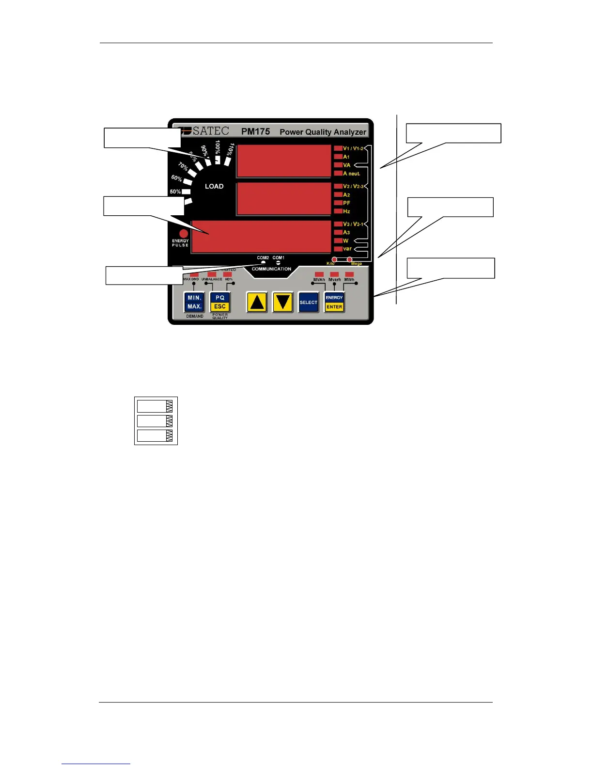
Numeric LED Display
The meter has a simple user interface that allows you to view
numerous measurement parameters by scrolling through
different display pages. The numeric LED display shows up to
three parameters at a time. Small rectangular or triangular
LEDs at right and below the display indicate the displayed
parameters and their measurement units.
The display layout may change depending on the meter type
and mode of operation. There are three modes of display
operation: data display, status display, and programming
mode display.
Load Bar Graph
The load bar graph displays the amount, in percent (40% to
110%), of the present current load with respect to user-defined
nominal load current. The reference nominal current can be
set up in amps through the Display Setup menu. If it is set to 0
(default), the current load is referenced to the specified CT
primary current.