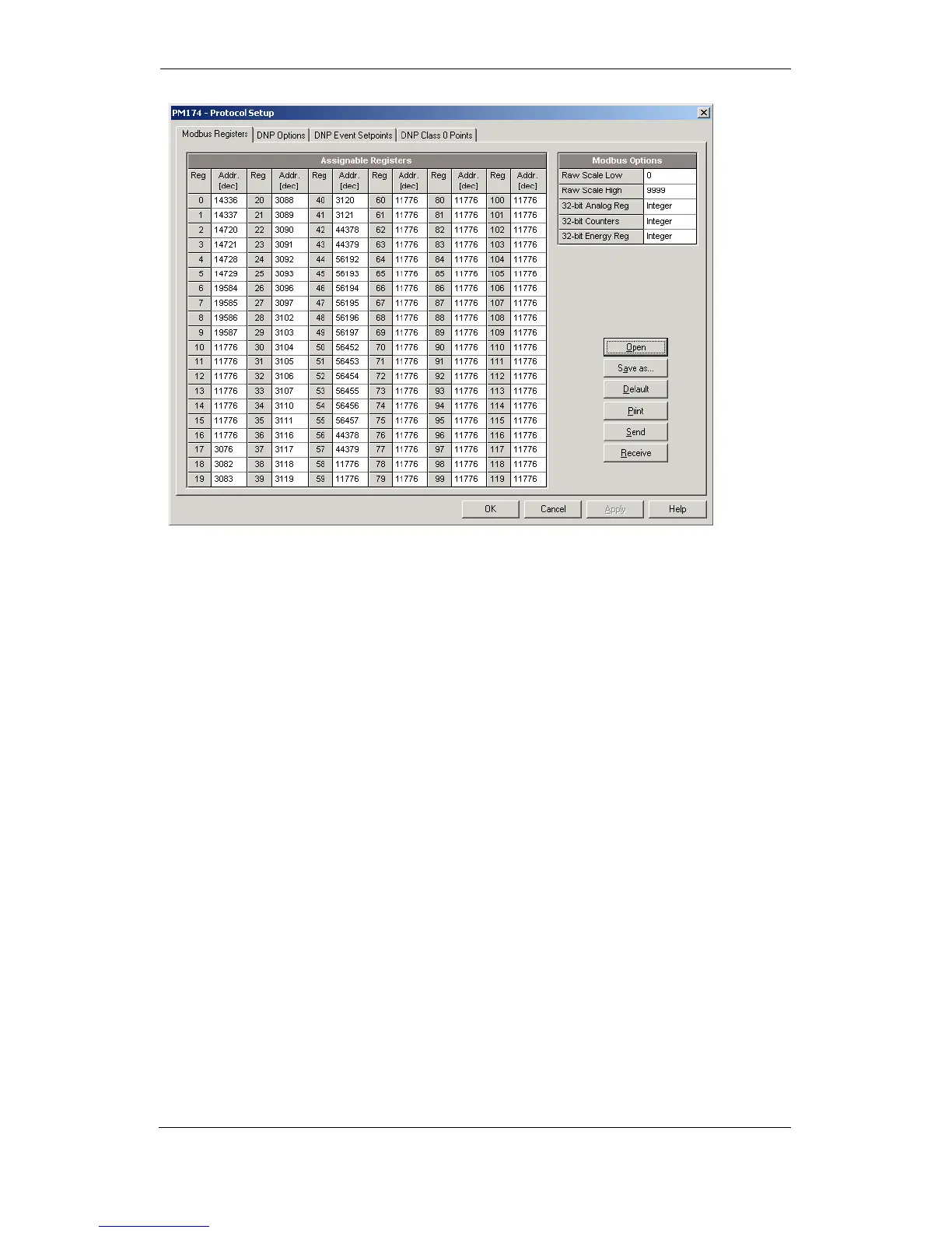
Initially these registers are reserved and none of them points
to an actual data register. To build your own Modbus register
map:
1. Select Protocol Setup from the Meter Setup menu and
click on the Modbus Registers tab.
2. Click on the Default button to cause the assignable
registers to reference the actual default meter register
11776 (0 through 119 are not allowable register
addresses for re-mapping).
3. Type in the actual addresses you want to read from or
write to via the assignable registers. Refer to the PM175
Modbus Reference Guide for a list of the available
registers. Notice that 32-bit Modbus registers should
always start at an even register address.
4. Click Send to download your setup to
the meter.
Configuring DNP3
DNP Options can be changed both via DNP3 and Modbus.
Refer to the PM175 DNP3 Reference guide for information on
the protocol implementation and a list of the available data
points.
DNP Options
To view or change the factory-set DNP options, select Protocol
Setup from the Meter Setup menu and click on the DNP
Options tab.