EasyManuals Logo

Satec PM175 User Manual

Satec PM175
168 pages
To Next Page IconTo Next Page
To Previous Page IconTo Previous Page
Page #20 background imageLoading...
Page #20 background image
Chapter 2 Installation
Electrical Installation
20
Series PM175 Powermeters
Wiring Diagrams
For AC input ratings, see “Technical Specifications” in
Appendix A.
The following wiring configurations are available in the meter:
Wiring Configuration
(See Basic Device Settings in Chapter 3)
Setup Code
Figure
3-wire 2-element Direct connection using 2 CTs
3dir2
2-17
4-wire Wye 3-element direct connection using 3 CTs
4Ln3 or 4LL3
2-18
4-wire Wye 3-element connection using 3 PTs, 3 CTs
4Ln3 or 4LL3
2-19
3-wire 2-element Open Delta connection using 2 PTs, 2 CTs
3OP2
2-20
4-wire Wye 2½ -element connection using 2 PTs, 3 CTs
3Ln3 or 3LL3
2-21
3-wire 2½ -element Open Delta connection using 2 PTs, 3 CTs
3OP3
2-22
4-wire 3-element Delta direct connection using 3 CTs
4Ln3 or 4LL3
2-23
3-wire 2½-element Broken Delta connection using 2 PTs, 3 CTs
3bLn3 or 3bLL3
2-24
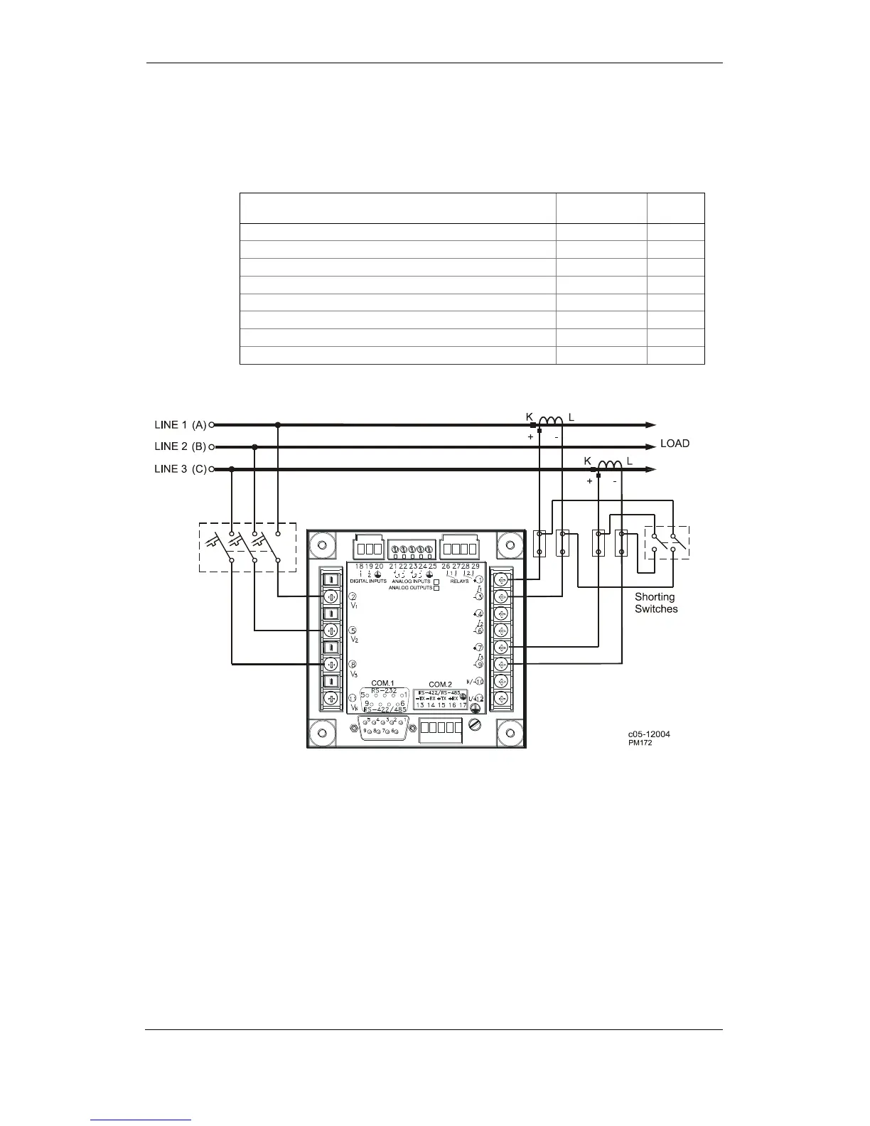
Figure 2-17 3-Wire 2-Element Direct Connection Using 2 CTs.
Wiring Mode = 3dir2

Table of Contents

Questions and Answers:

Question and Answer IconNeed help?

Do you have a question about the Satec PM175 and is the answer not in the manual?

Satec PM175 Specifications

General IconGeneral
BrandSatec
ModelPM175
CategoryMeasuring Instruments
LanguageEnglish

Related product manuals