SATEL Installation and Programming Manual 9
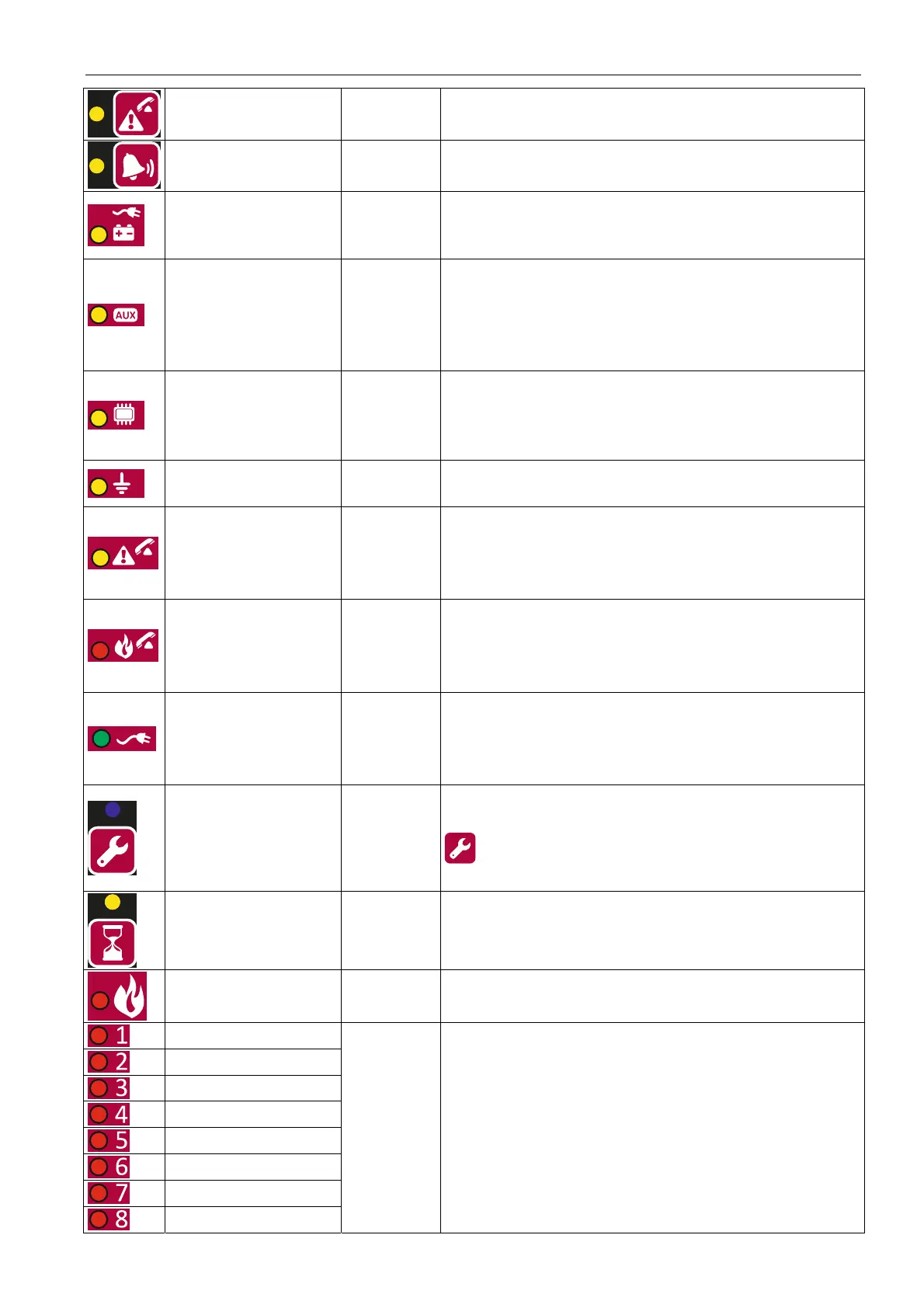
fault routing
yellow
blinking – output fault (short-circuit or break)
ON – output is disabled or is being tested
sounders
yellow
blinking – sounder fault (short-circuit or break)
ON – sounders are disabled or are being tested
power yellow
blinking – power supply failure (loss of 230 V AC
mains, missing battery, low battery, high battery
resistance)
auxiliary devices yellow
blinking – programmable input fault (short-circuit
or break), fault signaled by a device connected to
programmable input, power output fault
(overload), repeater panel or CSP-ETH module
not present, repeater panel fault
system yellow
blinking – control panel hardware fault,
microprocessor-based system fault, corrupted
data in control panel memory, or alarm log
overflow
earth fault yellow
blinking – earth fault in one of the circuits of fire
alarm system
fault routing
yellow
blinking – fault warning routing output is active
(no confirmation of transmission)
ON – fault warning routing output is active and
transmission is confirmed
fire routing red
blinking – fire alarm routing output is active (no
confirmation of transmission)
ON – fire alarm routing output is active and
transmission is confirmed
power green
ON – control panel is supplied from 230 V AC
mains
blinking – control panel is supplied from a battery
(no 230 V AC supply)
service blue
slow blinking – access level 2
fast blinking – waiting for code entry after the
key is pressed
ON – access level 3 (programming)
delays yellow
ON – two-stage alarm mode is enabled (second
stage alarm is delayed)
fire red
blinking – fire alarm
ON – fire alarm acknowledged by the operator
fire in zone 1
fire in zone 2
fire in zone 3
fire in zone 4
fire in zone 5
fire in zone 6
fire in zone 7
fire in zone 8
red
slow blinking – pre-alarm
fast blinking – first alarm
ON – next alarm
 Loading...