SATEL Installation and Programming Manual 15
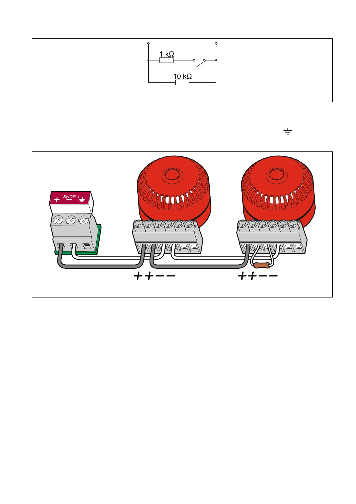
Fig. 10. The way of connecting resistors in the case of programmable input circuit.
5.2.3 Sounders
The fire alarm control panel comes with two sounder outputs. It is not required to use the
screened cable for connection of the sounders. For both outputs, a dedicated terminal for
connecting the screen is situated next to the pair of terminals with their polarity indicated.
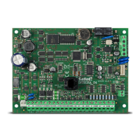
Fig. 11. Connecting sounders to the control panel – an example.
The sounder circuit should be terminated with a 10 kΩ resistor (the resistor can be screwed
to the terminals of the last sounder in the circuit). If the output is not used, the resistor should
be screwed directly to the output terminals.
5.2.4 Outputs to the routing equipment
The control panel is provided with an output to the fire alarm routing equipment and an output
to the fault warning routing equipment. Using the screened cable for making the connections
is not required. The circuit should be terminated with a 10 kΩ resistor. If the output is not
used, the resistor should be screwed directly to the output terminals. The control panel
program makes it possible to deactivate one or both outputs, if they are not in use (if so,
screwing the resistor to the terminals is not required).
5.2.5 Relay outputs
The CSP-108 and CSP-208 control panels have 8 relay outputs each, and the CSP-104
and CSP-204 control panels – 4 outputs. The relay outputs can control external devices.
5.2.6 Power outputs
The control panel is provided with two power outputs. The output marked AUX is a dedicated
power supply output for the CSP-ETH module. The output marked 24 V can be used to
power the external devices which require 24 V DC voltage supply. The output can only be
used during an alarm.