40 CSP-204 ● CSP-208 ● CSP-104 ● CSP-108 SATEL
8.3 Installation of the repeater panel
Disconnect power before making any electrical connections.
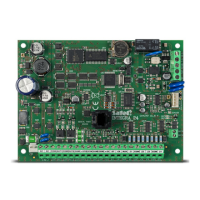
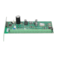
8.3.1 Mounting the repeater panel
The repeater panel should be mounted in the same way as the control panel (p. 11).
8.3.2 Connections
1. Connect the A, B and COM terminals to the communication bus (see: C
OMMUNICATION
BUS
,
p.
16).
2. Connect the main supply (see: M
AIN POWER SUPPLY
, p. 16).
Note: The repeater panel must be connected to the same PE protective circuit as the control
panel.
3. Connect the backup power supply (see: B
ACKUP POWER SUPPLY
, p. 18).
9. CSP-ETH module for communication with the virtual panel
The CSP-ETH module is an extra, optional component for fire alarm control panels. It allows
the possibility of remotely viewing the control panel state by means of a computer with
access to the Ethernet (TCP/IP) network. A Web browser and the Java Virtual Machine must
be installed on the computer.
FreeRTOS is used in this product (www.freertos.org).
Note: The device is only designed for use in the local area networks (LAN). It cannot be
connected directly to public computer networks (MAN, WAN). For connection to
a public network you must use an xDSL router or modem.
9.1 Electronics board description
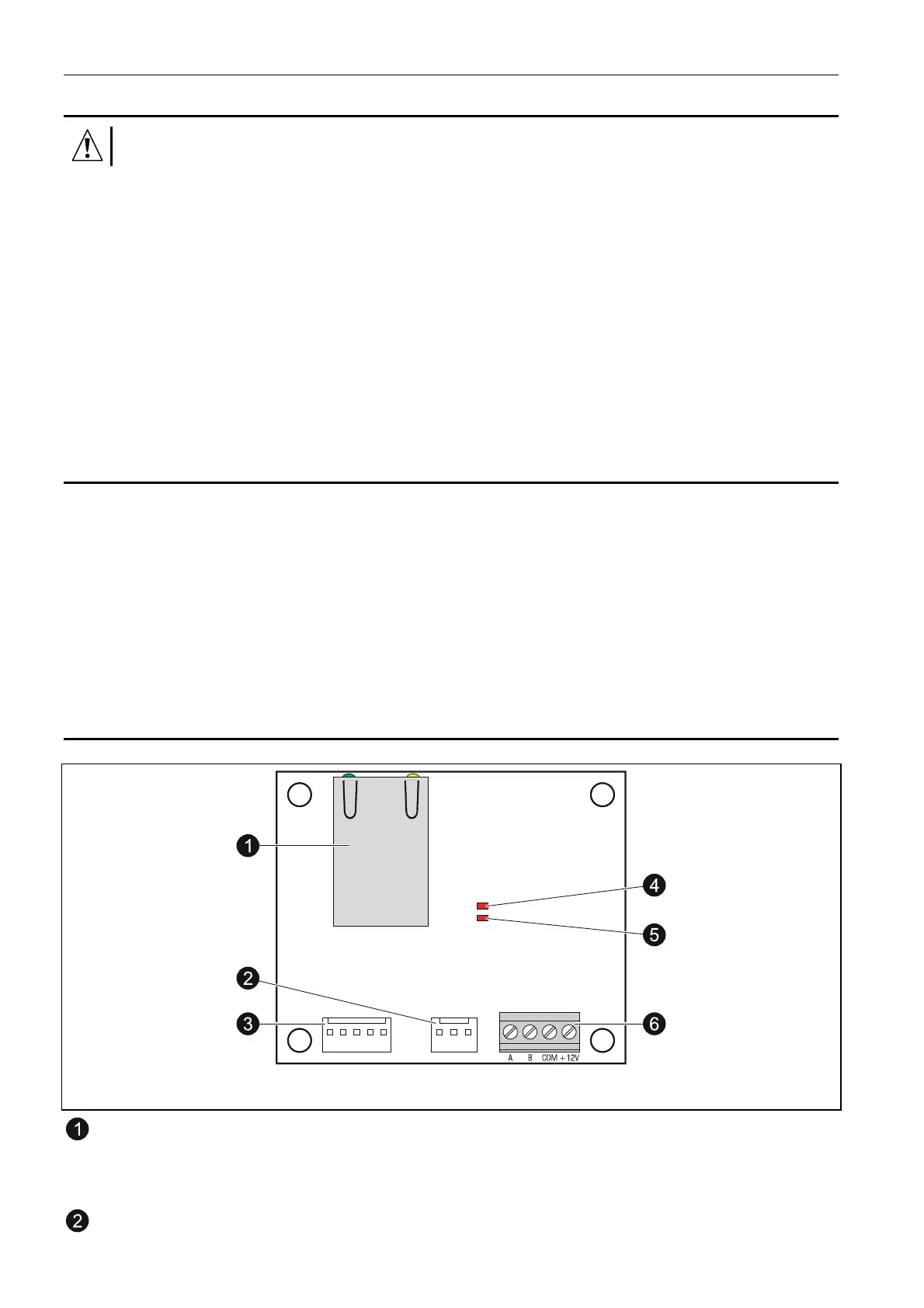
Fig. 21. View of the CSP-ETH module electronics board.
RJ-45 socket for connecting the module to Ethernet network. 100Base-TX standard
compatible cable should be used. The socket has two built-in LEDs. The green one
indicates connection to the network and data transmission, and the yellow one
- negotiated transmission rate (ON: 100 Mb; OFF: 10 Mb).
unused connector.

 Loading...