SATEL Installation and Programming Manual 41
unused connector.
LED indicating whether the module is supported by the control panel:
blinking – module is not supported;
ON – module is supported.
LED indicating whether the virtual panel is active:
blinking – virtual panel is not active;
ON – virtual panel is active.
terminals:
A, B - communication bus terminals.
COM - common ground.
+12V - power input.
9.2 Installation
Disconnect power before making any electrical connections.
1. Remove the control panel mainboard module from its mountings (see: M
OUNTING THE
CONTROL PANEL
,
p. 11).
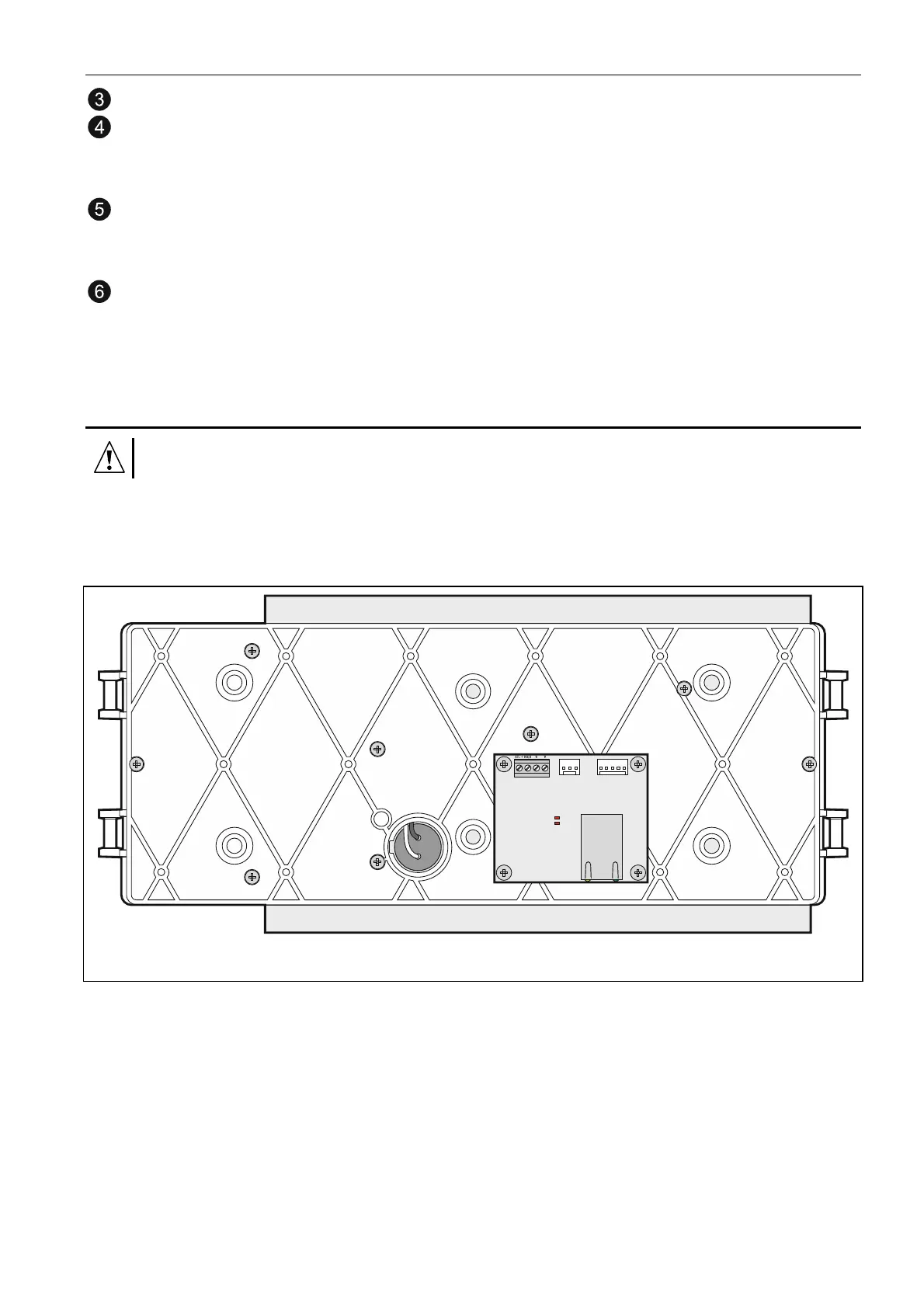
2. Attach the CSP-ETH module with screws to the underside of control panel mainboard
module.
Fig. 22. Mounting the CSP-ETH module.
3. Connect the module A, B and COM terminals to the communication bus (see:
C
OMMUNICATION BUS
,
p.
16).
4. Connect the module +12V and COM terminals to the control panel AUX terminals (+12V
to +; COM to -).
5. Install the control panel mainboard module in its mountings inside the enclosure.
6. Connect the Ethernet network cable to the module RJ-45 socket. If the network cable is
missing, the module will not start up.
Note: The module programming should be performed through the fire alarm control panel to
which the module is connected.