INSTALLATION
MANUAL
© Scania CV AB 2018, Sweden
Components – Stage IV/Tier 4f and Stage III B/Tier 4i
01:07 Issue 17 en-GB 33
The sensor control units are connected to the EEC3 control unit in the reductant tank.
See Connecting the reductant tank
. The control units should be fitted on the frame so
that they are shielded from radiated heat and knocks. The attachment holes have a
diameter of 8.3 mm. The electrical cables between the sensors and the control units
must not be spliced. The NO
x
sensors and control units must not be painted.
If the ambient temperature at the NO
x
sensor control units is too high, the control
units may be damaged.
Maximum permitted ambient temperature at the NO
x
sensor control units is 90 C.
Measure the ambient temperature when installation is complete. Refer to 01:08
Measuring instructions for installation inspection.
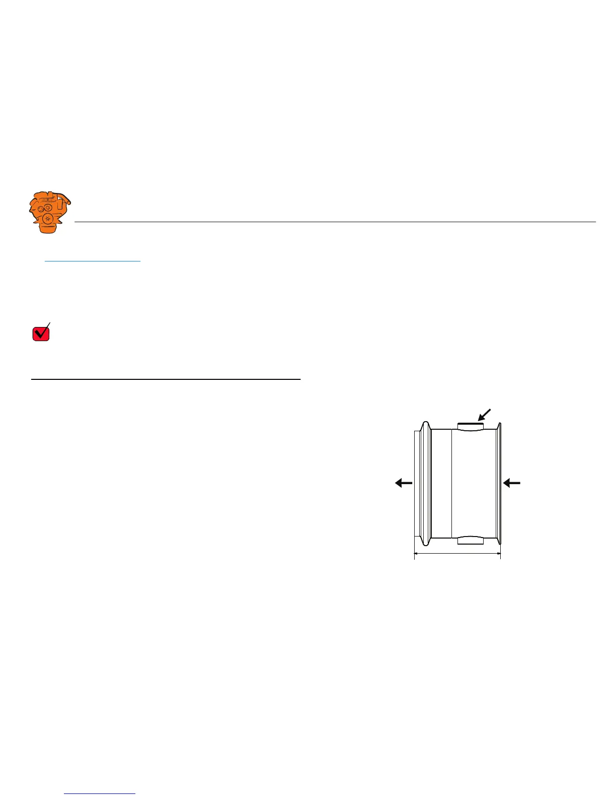
Position
Fit the supplied NO
x
adapter on the outlet side of the SCR catalytic converter. The
adapter has a connection for NO
x
sensor T115 (black electrical cable). The NO
x
adapter is available with different inside diameters for connection of different pipe
diameters downstream of the SCR system. The tightening torque for the V-clamp be-
tween the SCR catalytic converter outlet and the NO
x
adapter is 20 Nm.
100
340 441