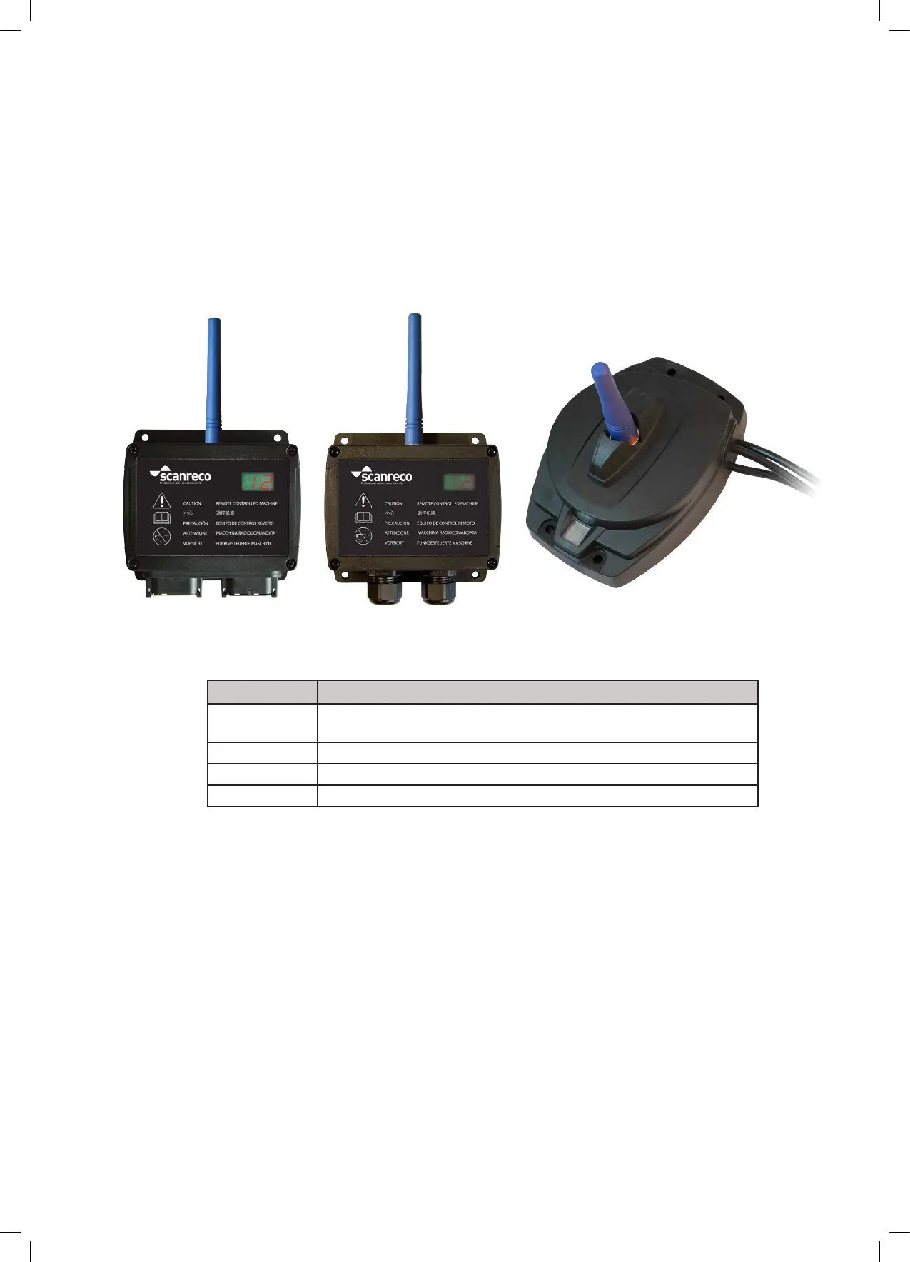
G5-M19A G5-R5/R10 G5-CAN
Model Functions
G5-M19A Two 12-pin Deutsch connectors. 19 Digital MOSFET outputs whereof
14 can be congured as digital inputs.
G5-R5 Two cable glands. 5 Relay outputs.
G5-R10 Two cable glands. 10 Relay outputs.
G5-CAN CAN-Bus output
6.2 Versions
The G5 Receiver exists in different versions. The main difference between the version types
is the output type which can be either MOSFET output, Relay output or CAN-Bus output.
Versions with MOSFET output have two 12-pin Deutsch connectors while versions with relay
output have cable glands with spring terminal block. The CAN version have cables with M12
connectors.
The G5 system is required to be congured prior to operation, refer to programming section
10 in this document for further information.
6.3 Functionality
17/33
 Loading...


