8 Installation recommendation
This chapter covers general recommendations for assembling of the G5 system.
ATTENTION: Assembly of the system in other ways than recommended in this chapter may
affect the systems performance and life-span and may void any warranties given.
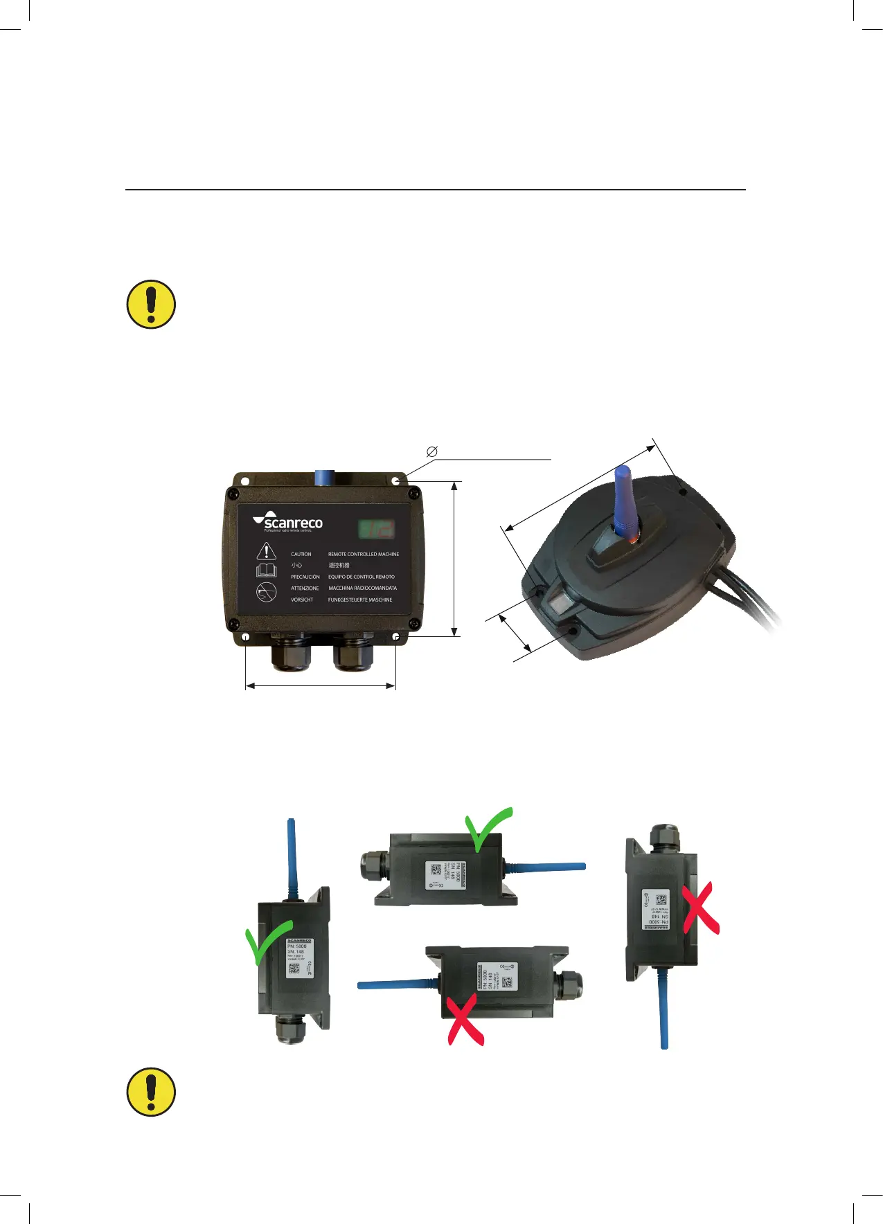
The Receiver should be installed using the mounting holes at the edges on the unit. Receivers
equipped with Deutsch connectors require M4 screws in the two lower holes.
The Receiver should be installed vertically or horizontally with with antenna facing upwards
or horizontally. The Receiver should never be assembled with cable glands / connectors facing
upwards or where it is exposed to accumulation of water, moisture and other debris.
Engineering note: Receivers equipped with Deutsch connectors require M4 screws in the two
lower holes.
8.1 General information
8.2 Assembly of the Receiver
101,5mm (4 in)
5,5mm (0,22 in)
104mm (4,09 in)
40mm
(1,57 in)
137mm (5,39 in)
Changes or modications not expressly approved by the party responsible for compliance could void the user’s authority to operate the equipment.
23/33
 Loading...


