After installation of the Receiver and the batteries have been inserted into the Transmitter,
the system should be fully operational with the default settings.
The default setting use button number 7 to turn on the system. Buttons 1-6 are mapped
to output 1-6. To turn off the Transmitter button 8 is used. The red stop button can also
be used to turn off the unit. To change the turn-on and turn-off buttons please refer to the
programming section.
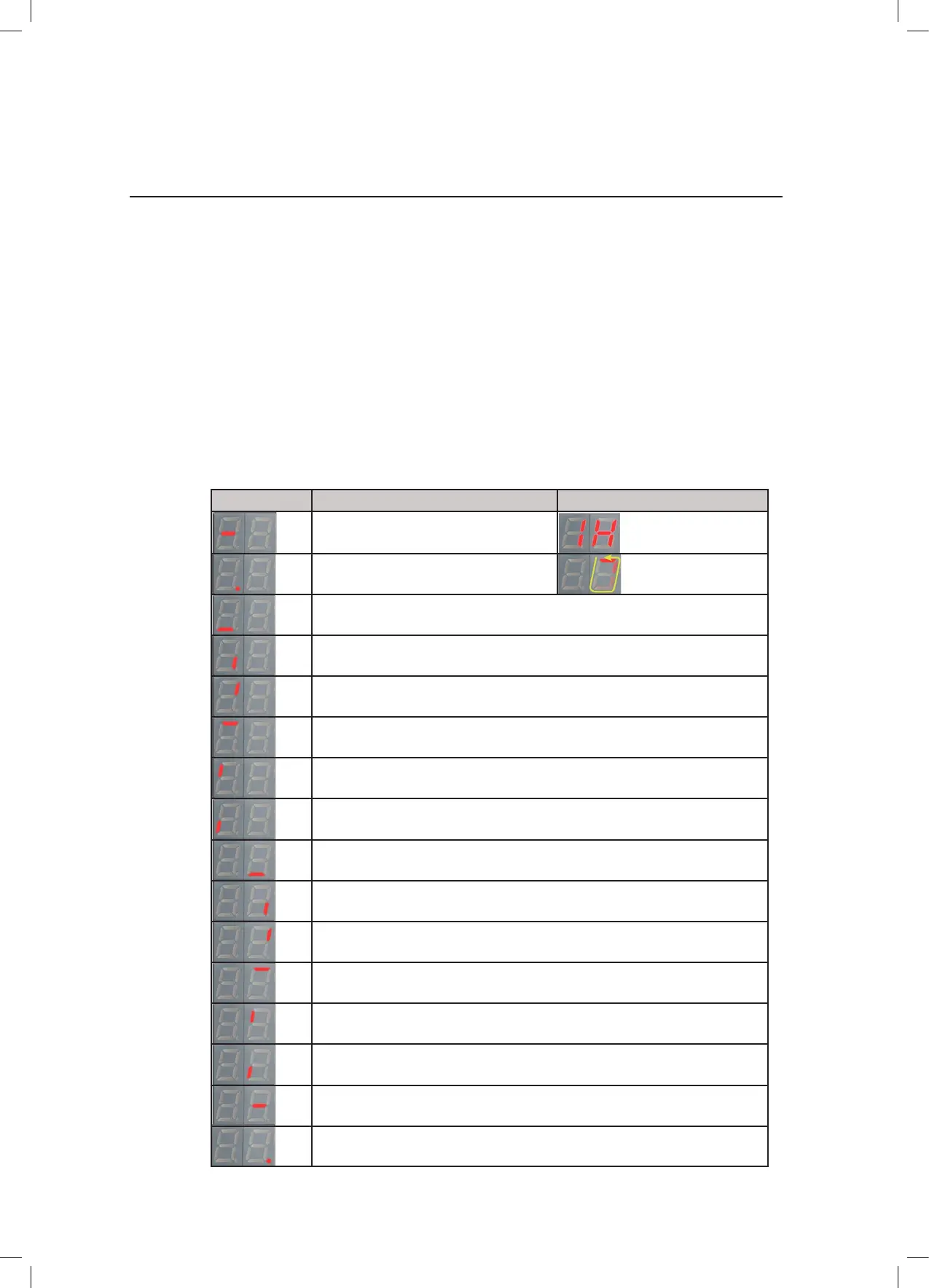
The LED display on the Receiver is used to indicate radio link or output activation. The list
below describes the different indications.
9 S
tartup and LED indication
G5 Receiver Meaning G5 Receiver CAN
Link is established
Standby
Output 1 Activated
Output 2 Activated
Output 3 Activated
Output 4 Activated
Output 5 Activated
Output 6 Activated
Output 7/15 Activated
Output 8/16 Activated
Output 9/17 Activated
Output 10/18 Activated
Output 11/19 Activated
Output 12 Activated
Output 13 Activated
Output 14 Activated
26/33
 Loading...


