Introduction
Schlage • L-Series service manual • 5
Introduction
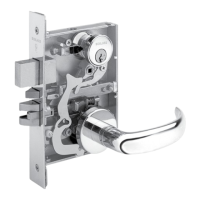
This manual contains a complete listing of parts and assemblies for L-Series mortise locks manufactured by Schlage Lock
Company. This edition lists components of L-Series locks manufactured aer June, 2001. All lock case covers are labeled
with the date of manufacture. Example: 8/15/13 = August 15, 2013.
Exploded views of each lock function and trim assembly are provided with accompanying charts to identify parts for
replacement purposes. Exploded views of trim are shown with parts for standard size doors. In addition, this manual
provides lock trim ordering procedures, cylinder length charts by door range, and all auxiliary components of the
L9000/LV9000, LM9300/LMV9300 and L400-Series mortise locks.
Standard features
Certifications L/LV9000: ANSI A156.13, 1994, Series 1000, Grade 1 Operational, Grade 1 Security, UL Listed for 3 hour fire door (except L9076
and L9077). With Interchangeable Core Cylinders: Grade 2 Security L400: ANSI A156.5, 2001, Grade 1, UL Listed for 3 hour fire
door.
Case size L/LV9000 and LM9300/LMV9300: 4M\zn" x 6Z\zn" x 1"; L400: 4M\zn" x 3B\," x 1"
Armor front L/LV9000 and LM9300/LMV9300: 1Z\v" x 8"; L400: 1Z\v" x 5Z>\cx"
Deadbolt 1" Throw stainless steel
Latchbolt C\v" Throw stainless steel with anti-friction tongue
Strike L/LV9000: 1Z\v" x 4M\,", Square corner, 1C\zn" lip, box; L400: 1Z\," x 3B\,", Square corner, box
Backset 2C\v"
Cylinder 6-Pin solid brass, keyed 6-pin, S123 keyway, keyed different (KD)*
Door range 1C\v" and up
Keys Two nickel silver cut keys per lock, 6-pin, S123 section*
Items specified in C keyway will be furnished with cylinders keyed 5-pin and with 5-pin keys unless otherwise specified.
NOTE: Locks are furnished with standard features unless otherwise specified.
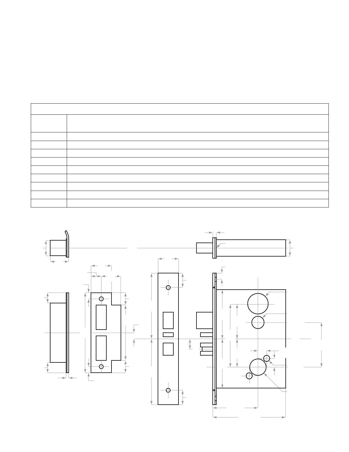
Strike
1¹⁄₄" (32)
or
1¹⁄₁₆"
(27)
1¹⁄₄"
(32)
1³⁄₁₆"
(30)
⁵⁄₈"
(16)
³⁄₈"
(10)
³⁄₈"
(10)
⁵⁄₈"
(16)
³⁄₈"
(10)
⁵⁄₃₂"
(4)
3"
(76)
2⁹⁄₆₄"
(54)
1²³⁄₃₂"
(44)
Cylinder
cut-out
Height
Line
2²³⁄₃₂
(69)
¹⁵⁄₁₆"
(24)
1¹⁄₈"
(29)
⁷⁄₃₂"
(6)
1" (25)
Bevel ¹⁄₈" in 2" (3 in 51)
2³⁄₄" (70)
Backset
4⁷⁄₁₆" (113)
⁵⁄₈"
(16)
³⁄₄"
(19)
³⁄₄"
(19)
⁵⁄₈"
(16)
Lock
Front
C
L
¹⁷⁄₃₂"
(14)
Mounting
Holes
Knob or Lever
Cut-out
Turn Piece
and
Occupancy
Indicator
3⁵⁵⁄₆₄"
(98)
3"
(76)
4"
(102)
4⁷⁄₈"
(124)
⁷⁄₈"
(22)
⁷⁄₈"
(22)
C
L
³⁄₈"
(10)
C
L
4"
(102)
C
L
C
L
3³⁄₈"
(86)
(Standard)
(Optional)