Assembly
44
10.00 | PGN-plus-P | Assembly- and Operating Manual | en | 389753
5.4.13.2 Mounting FPS-M8
To be able to mount the sensor, the gripper has to be retrofitted
with a special mounting kit.
Variant Dust-tight:
Before attaching the sensor, remove the sealing bolts from the
bracket. Before adjusting the control cam, unscrew the set-screw
from the side cover.
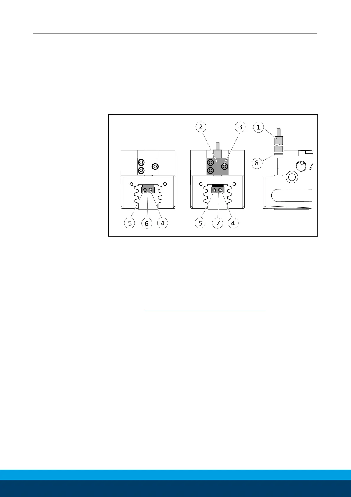
Ø Move product to the "gripper open" position.
Ø Loosen clamping spindle (4) and remove the switching cam (6)
for inductive sensing from the base jaw by turning the adjusting
spindle (5).
Ø Slide control cam (7) from the mounting kit into the base jaw.
Ø Screw the switching cam (7) into the base jaw by turning the
adjusting spindle (5) until the adjustment dimension I3 is
reached Setting dimensions for position sensors [
}
30].
Ø Fix the control cam (7) with the clamping spindle (4). It must not
be possible to move the control cam after assembly.
Ø For sizes 125-1, 200-1 and 200-2: Slide spacer (8) into the
bracket (2) to the stop.
Ø Slide the sensor (1) to the stop into the bracket (2).
Ø Tighten the screw (3) on the bracket (2).
Tightening torque: 0.2 Nm
Ø Adjust sensor (1), see assembly and operating manual of the
sensor.