Date Code 20010518 Settings 6-15
SEL-2020 Instruction Manual
Automatic Message Operation
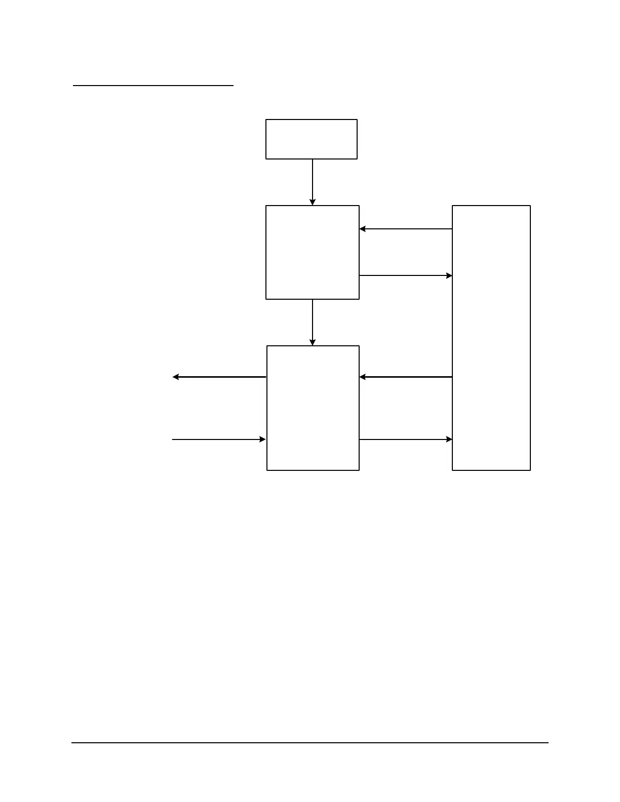
The messaging process is diagrammed in Figure 6.3.
Response Data
Clear Dx
or ARCHx Bit
Data
Assert
Dx or ARCHx Bit
Any Database
Bit(s)
Time
Processor
SEL
OGIC
Control Equation
Processor
Detects
Assertion of
Trigger Condition
Message
Generator
Sends Triggered
Message
Input Handler
Parses and Stores
Response
Database
Dx or Ax
Region
Message
Response
EIA-232
Port
EIA-232
Port
DWG: 2020lj22.vsd
Trigger
Figure 6.3: Automatic Message Operation Functional Block Diagram
The SEL
OGIC Control Equation Processor (Figure 6.3) detects the true or false status of the
trigger condition as defined in a SEL
OGIC Control Equation (using the ISSUEx setting). When
the condition becomes true, SEL
OGIC Control Equation Processor sets the Dx or ARCHx bit
(depending on whether it is a data or archive region of the database involved) and causes the
Message Generator to issue the message that you have defined with the auto-message setting.
See Section 7: SEL
OGIC Control Equations for more details about triggering.
The message issued may elicit a response. With the settings, you tell the SEL-2020 what data to
expect (including meter, ASCII floating point, and integer) and how to parse, validate, and store
the data. The data are then stored in the appropriate region of the database and the Dx or
ARCHx bit is cleared. If a response is not expected, the Dx or ARCHx bit is cleared upon issue
of the triggered message. See Section 8: Message Strings for details on strings.