3-10 Installation Date Code 20010518
SEL-2020 Instruction Manual
JUMPER SETTINGS
This subsection describes the hardware jumper selections available on the SEL-2020 Communca-
tions Processor, and the recommended procedures for making the jumper setting changes.
Main Board Jumpers
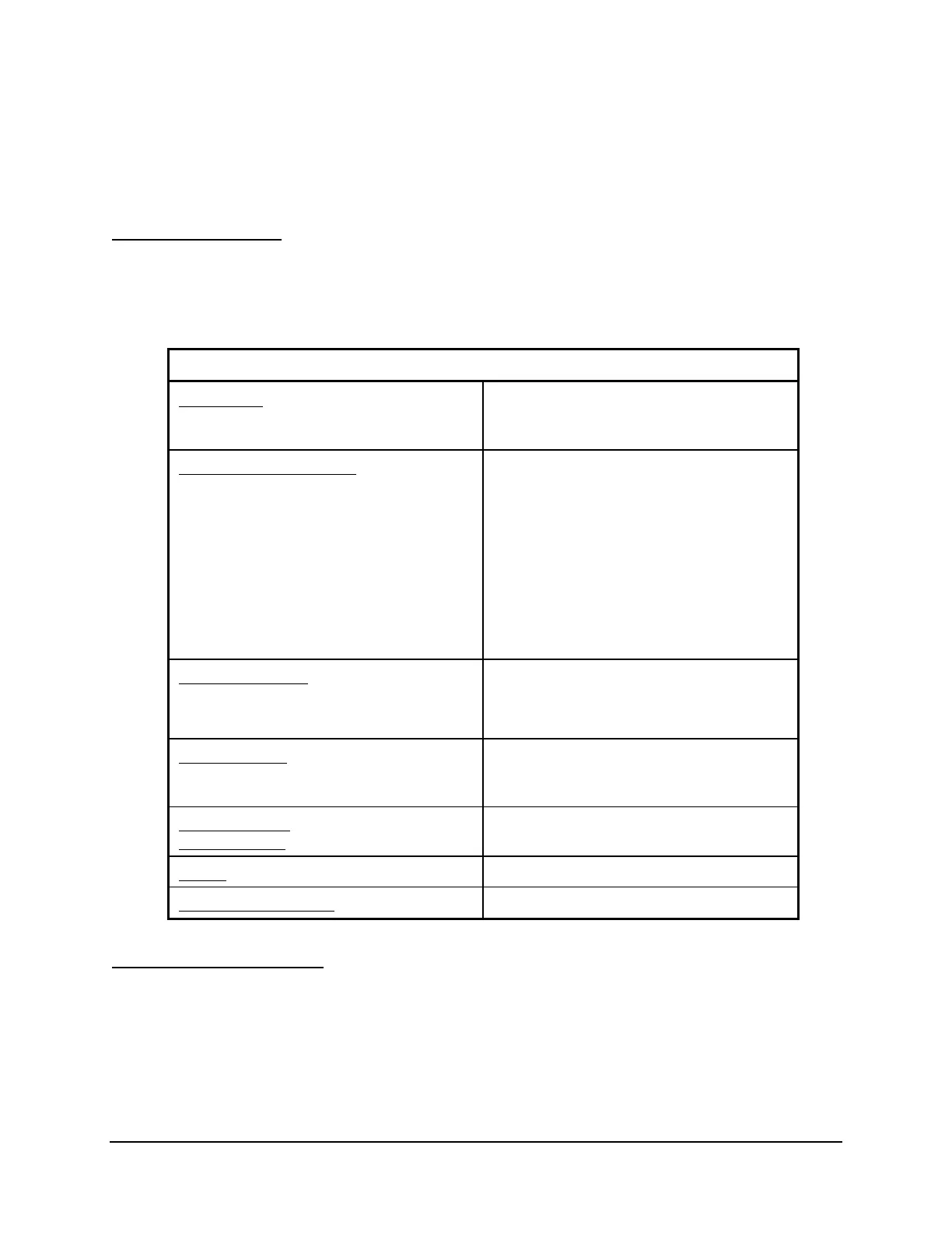
Set the main board jumpers to meet your requirements. See Table 3.4 for jumper functions and
positions. See Figure 3.2 for jumper locations on the main board.
Table 3.4: Main Board Jumper Positions
Function Install Jumpers At:
IRIG-B Input
Modulated
Demodulated (factory setting)
JMP2 2-3, JMP7 2-3(remove JMP1)
JMP1, JMP2 1-2, JMP7 1-2
Connect +5 Vdc to pin 1 on:
Port 1/ /Port 2
Port 3/ /Port 4
JMP6, Position A/ /JMP6, Position C
JMP5, Position A/ /JMP5, Position C
Port 5/ /Port 6
Port 7/ /Port 8
JMP4, Position A/ /JMP4, Position C
JMP3, Position B/ /JMP3, Position C
Port 9/ /Port 10
Port 11/ /Port 12
JMP6, Position B/ /JMP6, Position D
JMP5, Position B/ /JMP5, Position D
Port 13/ /Port 14
Port 15/ /Port 16
(factory setting = all off)
JMP4, Position B/ /JMP4, Position D
JMP3, Position A/ /JMP3, Position D
Alarm Contact Form
Form A
Form B (factory setting)
JMP8
(20 AWG wire) A to Common
(20 AWG wire) B to Common
Port F Baud Rate
2,400 baud, RTS/CTS = N, XON/XOFF = Y
Selected by SET P settings.(factory setting)
(This jumper is read on power-up.)
JMP9 A Installed
JMP9 A Removed
Password Disable
Password Enable
(factory setting)
JMP9 B Installed
JMP9 B Removed
Unused
JMP9 C
Reserved - Do not install
JMP9 D
Input/Output Connections
If your SEL-2020 is equipped with the optional I/O board, it has a terminal strip that extends
nearly the full width of the SEL-2020, near the top of the rear panel.