Date Code 20010518 SELOGIC Control Equations 7-1
SEL-2020 Instruction Manual
SECTION 7: SELOGIC
®
CONTROL EQUATIONS
INTRODUCTION
This section covers SELOGIC
®
Control Equation operation, inputs, syntax, and outputs.
SEL
OGIC Control Equations are central to many of the functions of the SEL-2020. They are
defined within the global (SET G), auto-message (SET A), and logic (SET L) settings described
in Section 6: Settings.
OPERATION
SELOGIC Control Equations are at the heart of the more advanced functions of the SEL-2020
because they define when operations are to take place, and they control contact outputs on the
optional I/O board. Many conditions detected by the device are represented by Boolean values
or bits that are used in these equations. You can assign the value of one bit to an output bit,
which has some pre-defined use. You can also use Boolean equations to combine multiple input
bits to drive a specified output. You will find examples of these equations later in this section.
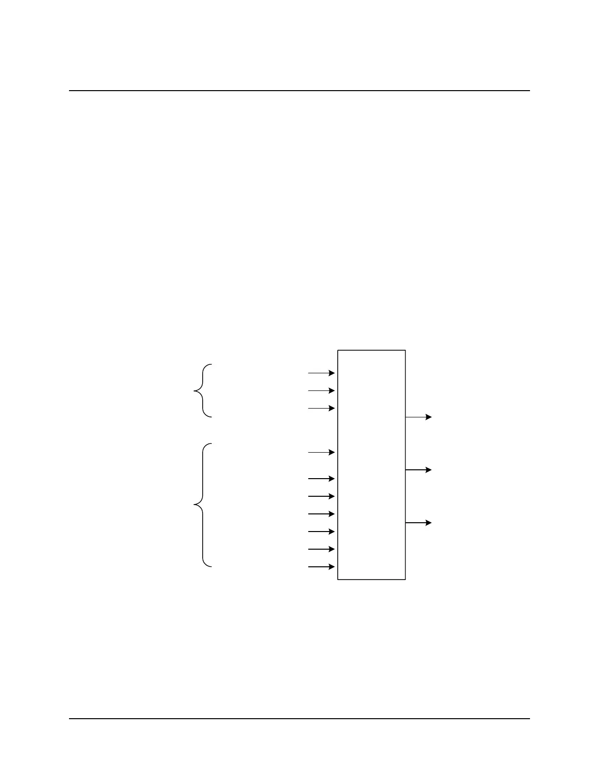
Figure 7.1 illustrates the SEL
OGIC Control Equation data flow.
Global
Elements
Port-Specific
Elements
Day-of-Week Inputs
Optional I/O
Intermediate Elements
User-Defined
Messages Receipt
Select-Before-Operate Bits
Operate Bits
SEL Relay Targets
Special Status Bits
Arbitrary Database Bits
Time Inputs
Intermediate
SEL
OGIC
Elements (SET G, SET L)
Optional I/O
Contact Output
Control (SET G)
Output Message
Triggers (SET A)
SEL
OGIC
Control
Equations
2020_07
Figure 7.1: SELOGIC Control Equations Inputs and Outputs
SEL
OGIC Control Equation inputs include the current time, global elements (as seen by executing
the TAR G command), local elements (as seen by executing the TAR n command), and arbitrary
database bits.