5-16 Applications Date Code 20000421
SEL-251, -2, -3 Instruction Manual
Summary of Figure 5.9
In general, for a phase-to-phase fault on the secondary side of a delta-wye transformer, the
following primary current relationship is true:
I x I
x I x I
P
P
=
=
2
15 3
2
2
.
Thus, for this case, the negative-sequence overcurrent elements have the same sensitivity as a
primary phase overcurrent element (e.g., the fuses for the delta-wye transformer) if the negative-
sequence overcurrent element pickup value is a factor of 1.5 times the primary phase overcurrent
element pickup value.
UNDERFREQUENCY LOAD SHEDDING INPUT
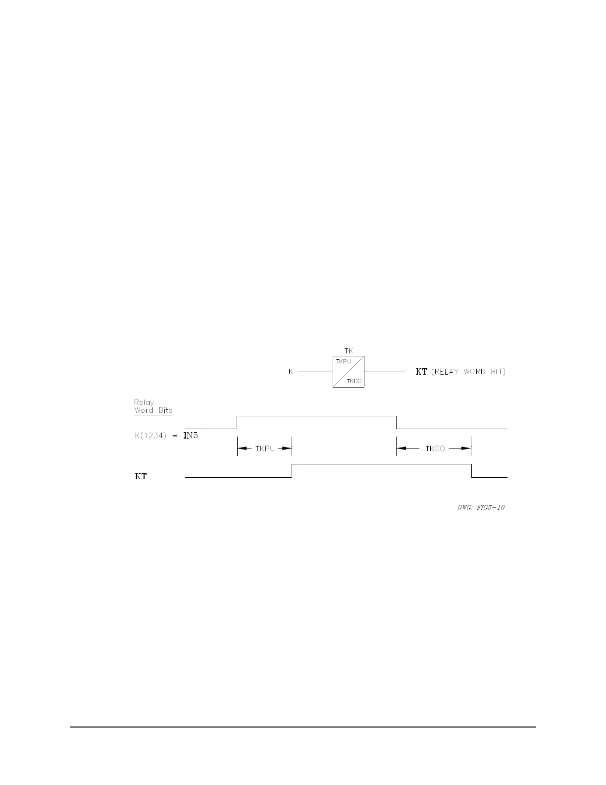
Relay Word inputs IN5 and IN6 can be used as time-qualified underfrequency load shedding
inputs. The output of an underfrequency relay is wired into IN5 or IN6.
Using SELOGIC Control Equations:
K(1234) = IN5
Figure 5.10: Input IN5 Qualified by Time TKPU
Time TKPU qualifies the underfrequency input condition.
Continuing with SELOGIC Control Equations:
TR(1246) = KT+... (TR is the programmable trip condition)
close TRIP output contacts = TR + ...
Relays on different feeders can have different TKPU time delay pickup settings so certain
feeders are tripped before others during a system underfrequency condition.


 To Next Page