Date Code 20000421 Applications 5-17
SEL-251, -2, -3 Instruction Manual
UNDERVOLTAGE LOAD SHEDDING
An undervoltage load shedding condition is possible by time qualifying the 27 Relay Word bit.
Using SELOGIC Control Equations:
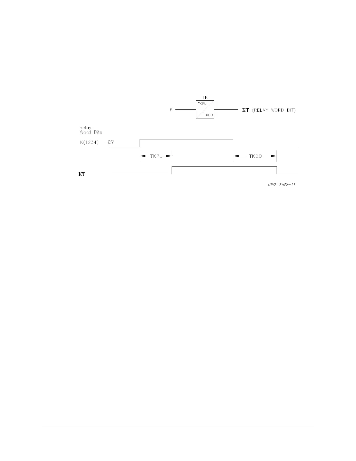
K(1234) = 27
Figure 5.11: Element 27 Qualified by Time TKPU
The TKPU time qualifies the undervoltage condition.
Continuing with SELOGIC Control Equations:
TR(1246) = KT+... (TR is the programmable trip condition)
close TRIP output contacts = TR + ...
A system undervoltage condition is a three-phase phenomenon, so the 27 element should be set
three-phase sensitive (setting 27C = 3). Set high- and low-set limits for 27 (27H and 27L),
according to system conditions.
BREAKER FAILURE
Use the TF bit in the Relay Word to create a breaker failure scheme.
Using SELOGIC Control Equations:
A1(1234)= TF
Output contact A1 operates as a breaker failure output. Breaker failure applications need the
following setting relationship.
TFT (Trip Failure Time) > TDUR (Trip Duration Time)

 Loading...


