6-10 Installation Date Code 20000421
SEL-251, -2, -3 Instruction Manual
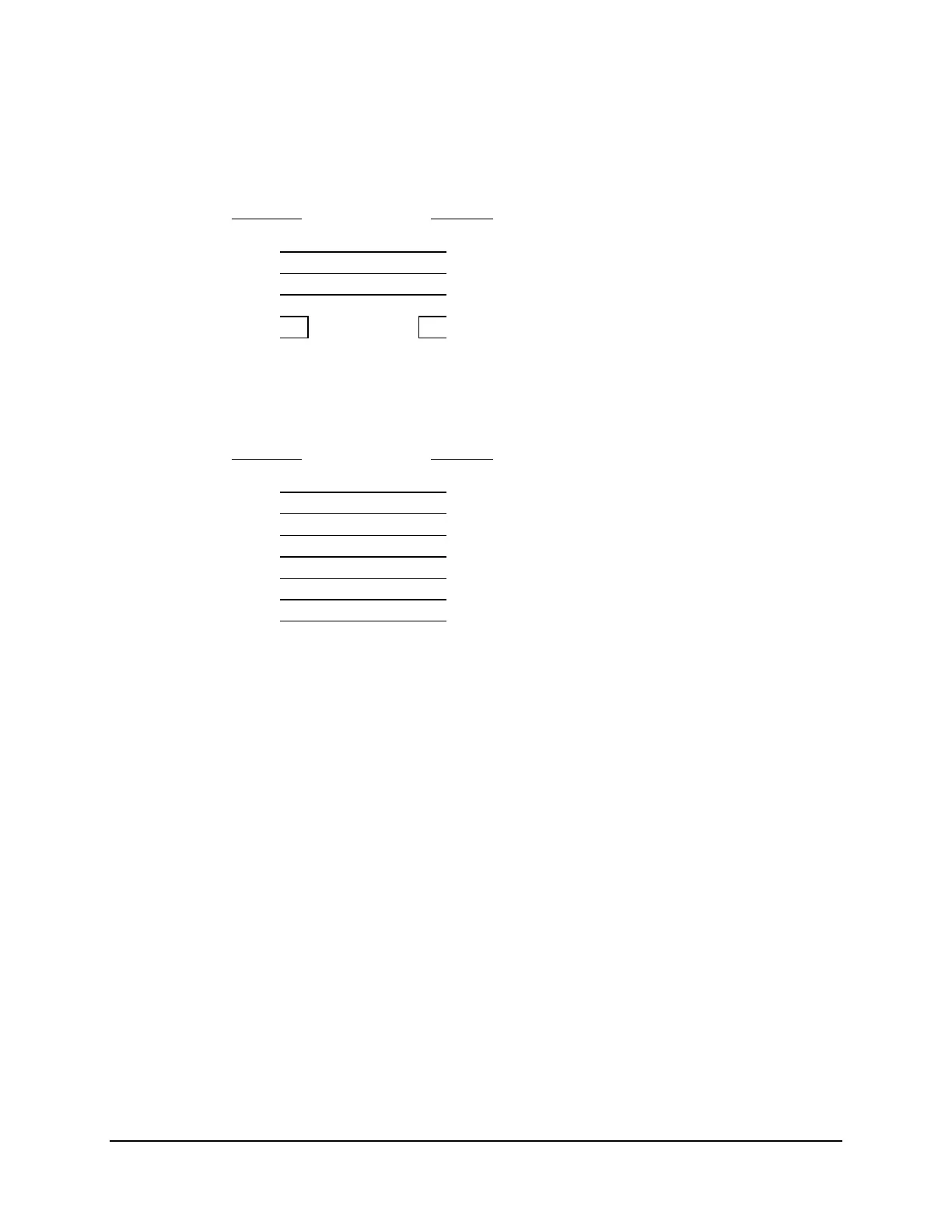
3 TXD
2 RXD
5 GND
8 CTS
7 RTS
4 +IRIG
†
†
Cable 272A
Data Only
SEL-2020 SEL-251
Cable 273A
Enhanced Data and IRIG-B
SEL-2020 SEL-251
* DTE = Data Terminal Equipment (Computer, Terminal, Printer, etc.)
** DCE = Data Communications Equipment (Modem, etc.)
†
When JMP13 and JMP14 are bridged.
IRIG-B Input Description
The port labeled J201/AUX INPUT receives demodulated IRIG-B input. Pin definitions appear
in Table 6.1.
On the plug-in connector model, Ports 1 and 2R may be configured to accept demodulated
IRIG-B input. When JMP13 and JMP14 are bridged, pins 6 and 4 will accept -IRIG-B and
+IRIG-B, respectively. See Table 3.2 for port pinouts.
The actual IRIG-B input circuit is a 56 ohm resistor in series with an optocoupler input diode.
The input diode has a forward drop of about 1.5 volts. Driver circuits should put approximately
10 mA through the diode when "on."
The IRIG-B serial data format consists of a one second frame containing 100 pulses and divided
into fields. The relay decodes the second, minute, hour, and day fields and sets the internal relay
clock accordingly.
RXD 2
TXD 3
GND 5
RTS 7
CTS 8
RXD 2
TXD 3
GND 5
RTS 7
CTS 8
+IRIG 4
-IRIG 6
3 TXD
2 RXD
5 GND
8 CTS
7 RTS