7-8 Maintenance and Testing Date Code 20000421
SEL-251, -2, -3 Instruction Manual
Continued from previous page
Global settings
DEMR =Y CFT =60 TDUR =4 TFT =30 TGR =180
ITT =5 TIME1=15 TIME2=0 AUTO =2 RINGS=3
IN1 =SS1 IN2 =DT IN3 =RE IN4 =
IN5 =52A IN6 =
=>
The SET command descriptions in Section 3: Communications include a complete
explanation of the settings.
♦ ♦ Step 9
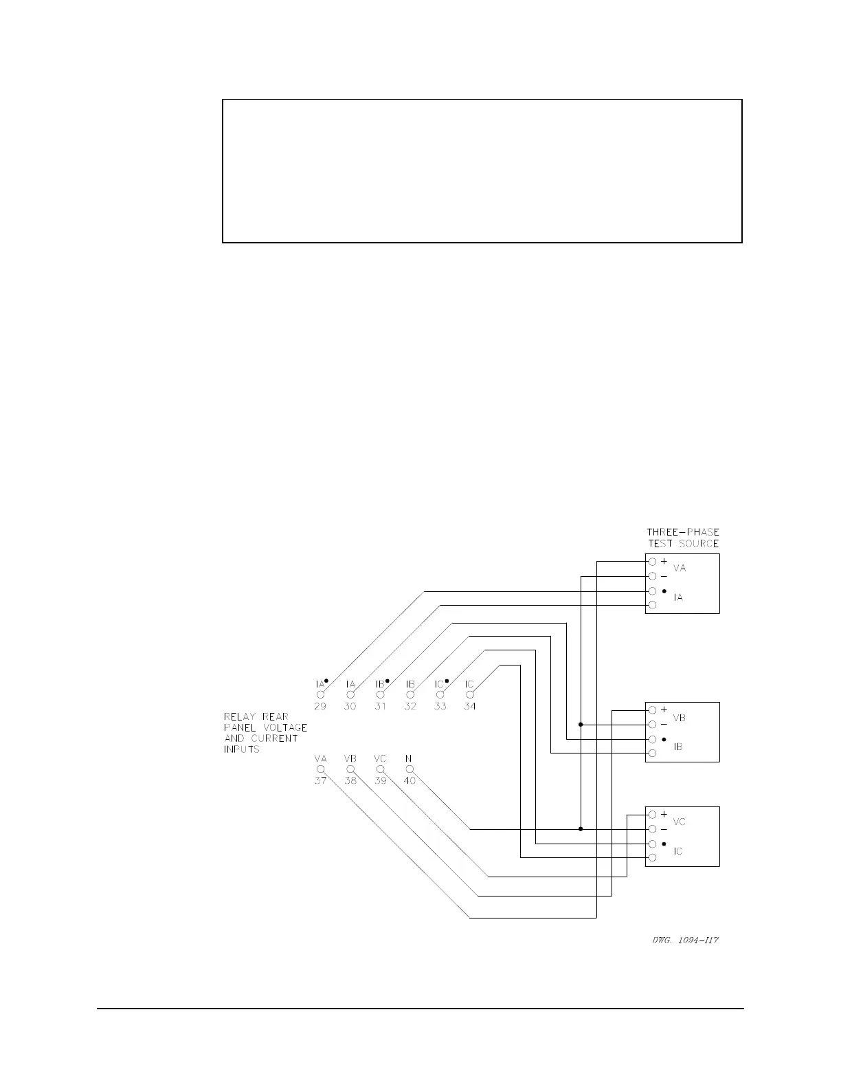
Purpose: Connect voltage and current sources to the relay.
Method: Turn power off and connect the sources of voltage and current to the rear panel
terminals of the relay as shown in Figure 7.3. Apply 69 volts per phase (line-to-
neutral) in positive-sequence rotation.
Set the A-phase current source to 2 amperes, at the same angle as the A-phase
voltage. Set the B-phase current source to 2 amperes, at the same angle as the B-
phase voltage. Set the C-phase current source to 2 amperes, at the same angle as the
C-phase voltage.
Figure 7.3: Three-Phase Voltage and Current Source Test Connections