7-12 Maintenance and Testing Date Code 20000421
SEL-251, -2, -3 Instruction Manual
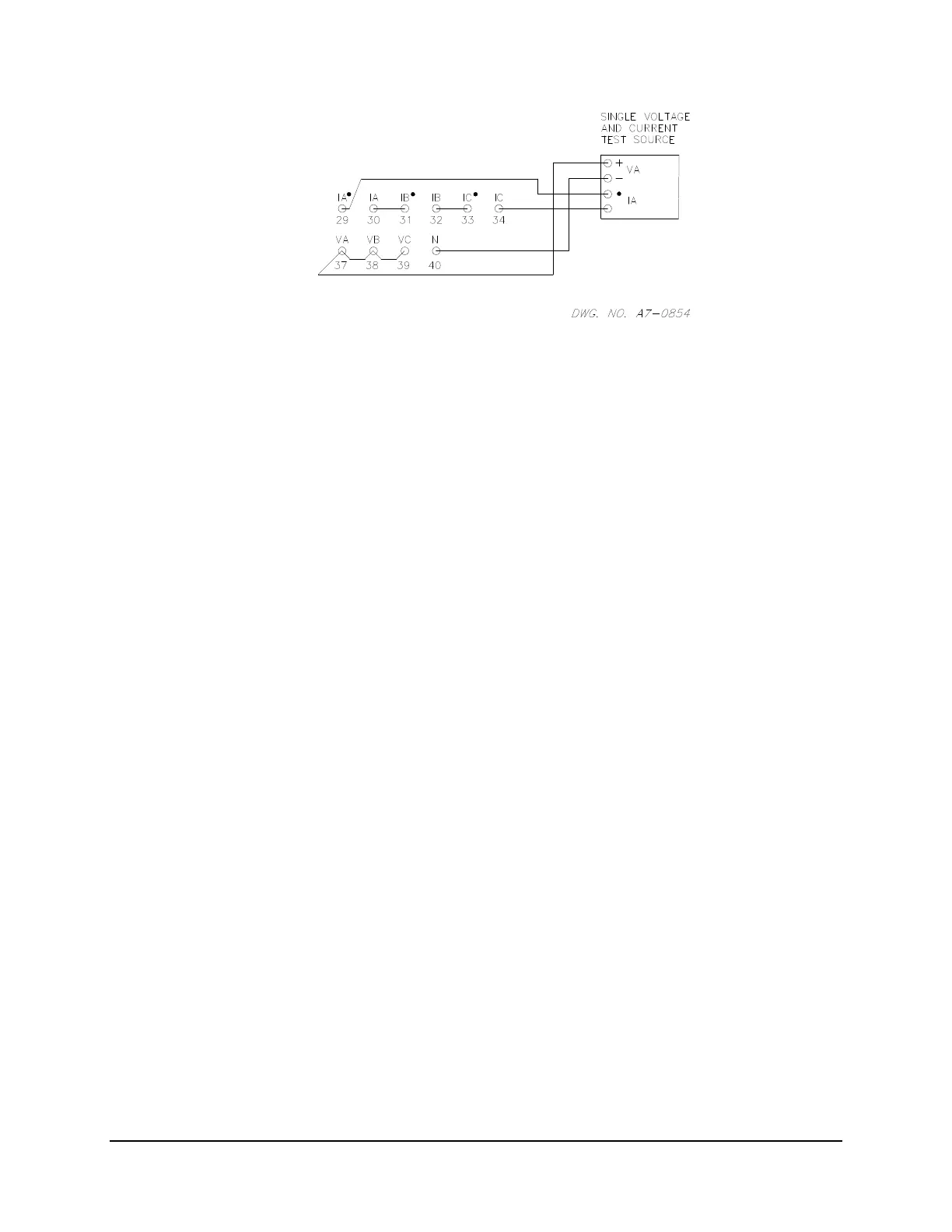
Figure 7.4: METER Test Connections
3. Apply a voltage of 50 Vac between the paralleled voltage inputs to the neutral
point and a current of five amperes through the three inputs. The phase angle of
the voltage and current source should be set to 0°.
4. Use the METER command to inspect measured voltages, currents, and power.
Voltages VA, VB, and VC should equal the applied voltage times the potential
transformer ratio setting. With the Example 21.6 kV distribution feeder settings,
you should obtain:
VA = VB = VC = (50 V)(180)
= 9000 V (±0.5%).
Voltages VAB, VBC, and VCA should read less than 135 V primary.
Similarly, currents IA, IB, and IC should equal the applied current times the
current transformer ratio. With the Example 21.6 kV distribution feeder settings,
you should obtain:
IA = IB = IC = (5 A)(120)
= 600 A (±1%).
Difference currents IAB, IBC, and ICA should be less than 12 amperes.
The power reading, P (MW) should read:
(VA(IA) + (VB)(IB) + (VC)(IC) = 16.20 MW.
The reactive power reading Q (MVAR) should be less than 0.3 MVAR.