EasyManua.ls Logo

Schwing CPC III - User Manual

Default Icon
50 pages
Print Icon
To Next Page IconTo Next Page
Loading...
1
Operation
CPC III Manual
Installation Instructions ...................................3
Control Panel ................................................... 3
Scanreco Radio ...............................................4
Oil Temperature Sensor ...................................4
Rear Control Panel ..........................................4
Important Notes ...............................................5
CPC III (Concrete Pump Controller) ................ 6
HMI (Human Machine Interface) .....................7
Navigation Pane ..............................................7
LCD Screens .....................................................8
Homepage Screen - with installed options ......8
Menu Screen ...................................................8
Module and PLC I/O Screens .......................... 9
INPUTS St Screen ...........................................9
OUTPUTS St Screen .......................................9
INPUTS Ex Screen .......................................... 9
OUTPUTS St Screen .......................................9
OUTPUTS Ex Screen ....................................10
System Voltage Screen .................................10
Keypad Screen ..............................................10
Radio Screen ................................................. 11
Proportional Settings Screen (Display) .......... 11
Proportional Settings Screen (Teach Mode) .. 12
Maintenance Screen - Password Prompt ......12
Maintenance Screen ......................................13
Conguration Screen ..................................... 13
Cable/Radio Remote Box ............................... 14
Status LCD Display .......................................15
98465796-00
Panel Assembly:
Schematic:
98458772
98455320
Boom Harness
(PBC)
Radio A
(PRADA)
Front Harness
(PFC)
Rear Harness
(PRC)
Programming Port
(PPPT)
I/O Harness
(PIOE)
Oil Temperature
(POTS)
Power
(PPG)
Pairing Port
Maintenance Switch
(PMS)
Radio C
(PRADC)
OFF
ON
In Maintenance mode, all CPC
safety features will be disabled
WARNING
ok
CPC III Manual
Question and Answer IconNeed help?

Do you have a question about the Schwing CPC III and is the answer not in the manual?

Overview

The SCHWING CPC III (Concrete Pump Controller) is a sophisticated, upgraded control system designed as a direct replacement for previous C32, CPC, and CPC2 systems. It integrates various functionalities to manage concrete pump operations, offering enhanced control, monitoring, and diagnostic capabilities. The system's design accommodates variations and revisions from original installations, making it adaptable to different configurations.

Function Description:

The CPC III acts as the central brain for the concrete pump, managing inputs from various sensors and operator controls to execute pump functions. It comprises several key components:

  • HMI (Human Machine Interface): This is the primary interface for operators to view and set machine parameters. It features an LCD screen, function buttons (F1-F4), an OK button, and navigation arrows for menu interaction. The HMI displays critical information such as RPM, hydraulic oil temperature, oil pressure, strokes per minute, and various status messages and error codes.
  • Control Panel: This houses the main CPC III controller, along with the HMI, local/remote switch, and maintenance switch. It serves as the central hub for connecting various harnesses (PPC, PRC, PFC, PBC) that link to different parts of the pump.
  • Scanreco Radio System: Similar to current Schwing BPLs/TMPs, the CPC III utilizes a Scanreco radio for remote operation. The receiver and antenna can be externally mounted, and the system supports pairing a transmitter to the receiver for unique assignment.
  • Operator Panel Keypad: This keypad, typically located at the rear of the unit, provides 15 buttons for controlling various pump functions. Each button has four indicator lights to provide feedback on active functions. Functions include agitator control (change direction, forward/reverse), horn/reset, oil cooler (auto/manual on), water pump (on/off), work lights (on/off), throttle (up/down), compressor (on/off), vibrator (auto/manual on/off), concrete pump (forward/reverse), and stroke limiter (increase/decrease).
  • Cable/Radio Remote Box: This handheld remote provides comprehensive control over the pump. It features an LCD display, joysticks for boom functions, throttle up/down switch, engine start/stop switch (disabled), horn/reset switch, boom speed selector switch, compressor/water pump switch, LED antenna light, emergency stop button (E-Stop), LED power/battery indicator light, agitator forward/reverse switch, power on button, concrete pump forward/reverse switch, stroke limiter dial, and vibrator on/off switch.

Important Technical Specifications:

While specific numerical values for all components are not explicitly detailed, the manual highlights several key aspects:

  • Electrical Schematic (98455320): This document provides the detailed wiring diagram for the CPC III system.
  • Panel Assembly (98458772): This is the part number for the main control panel assembly.
  • PLC (98391422): The Programmable Logic Controller is the core processing unit.
  • PDM (98465074): The Power Distribution Module manages power to various components.
  • HMI Software Version (V01.00.03T) and PLC Version (V00V): These indicate the software versions running on the HMI and PLC, crucial for troubleshooting.
  • System Voltage Screen: Displays voltage readings for VBBS, VBBR, VBBO, VBB15, VBB1, VBB2, VBB3, VBB4, and VBBrel, allowing monitoring of the system's electrical health.
  • Input/Output Signals: The system displays active input and output signals with green circles, along with supply voltage indicators and PLC temperature.

Usage Features:

  • Navigation: The HMI's navigation pane displays available functions and menu actions. Operators use function buttons and navigation arrows to move through screens and menu items.
  • Homepage Screen: Displays real-time operational data and status messages upon ignition.
  • Menu Screen: Provides access to various settings and status screens, including PLC I/O Status, Local Keypad, Radio, Prop Settings, Maintenance, and Configuration.
  • Proportional Settings Screen (Teach Mode): Allows adjustment of placing boom and stroke limiter parameters. This mode requires a password and involves calibrating joysticks for precise control.
  • Stroke Limiter Dial: On the remote box, this dial increases or decreases concrete pump strokes per minute in 10% increments.
  • Boom Speed Selector Switch: Adjusts the speed of boom sections (fast for folding/unfolding, slow for precise movements).
  • Pairing Transmitter to Receiver: A procedure is outlined for uniquely assigning a transmitter to a receiver, essential for radio remote operation.
  • Error Codes and Warning Messages: The HMI displays error codes and warning messages (e.g., "Water Tank Level Low," "Hydraulic Oil Temp High") with an audible horn. These messages aid in diagnosing and resolving operational issues.
  • Maintenance Switch: This switch, located on the control panel, puts the CPC III into bypass mode, disabling most safety features (including E-Stops) and setting RPMs to minimum values. It's intended for backup operation in case of system failure.

Maintenance Features:

  • Module and PLC I/O Screens: These screens display electronic input and output signals, helping in troubleshooting electrical issues by indicating active signals with green circles and showing supply voltage/PLC temperature.
  • Maintenance Screen: Accessible via a password, this screen displays parameters such as Concrete Pump Hours, Boom Hours, PTO Hours, Engine RPM Control, and Error Codes. It allows resetting hour counters and clearing error codes.
  • Configuration Screen: Used to enable or disable functionality for installed options (e.g., 1Channel E-stop, CPC2 Compatible, Stroke Counter, Oil Pressure Sensor, Agitator Disable, Boom Horn Disable, Boom Type, Max Engine RPM).
  • Initial Setup: Provides instructions for initial system setup, including turning on PTO, engaging the maintenance switch, checking fuses, and testing the system.
  • Troubleshooting: The manual provides tables for SOURCE - Input Error Codes, SOURCE - Output Error Codes, and CAUSE - Error Codes to assist in diagnosing problems. Display messages also offer guidance on various system states and potential issues.
  • Sensor Replacement: Instructions are provided for replacing the oil temperature sensor and concrete pressure sensor if necessary.
  • Harness Management: Emphasizes proper harness routing and securing with zipties, ensuring not to block the PDM cover.

The CPC III system is designed for robust performance and ease of maintenance, providing operators with comprehensive control and diagnostic tools for efficient concrete pump operation.
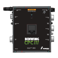
Schwing CPC III Specifications

General IconGeneral
BrandSchwing
ModelCPC III
CategoryIndustrial Equipment
LanguageEnglish

Related product manuals