18
Operation
CPC III Manual
Pairing Transmitter to Receiver
Pairing is necessary to get a unique assignment be-
tween a single Transmitter and a single Receiver. When
replacing either the Receiver or Transmitter in a system
follow the procedure below:
1. On the CPC III controller switch to Remote mode.
1. Switch o the transmitter and remove battery.
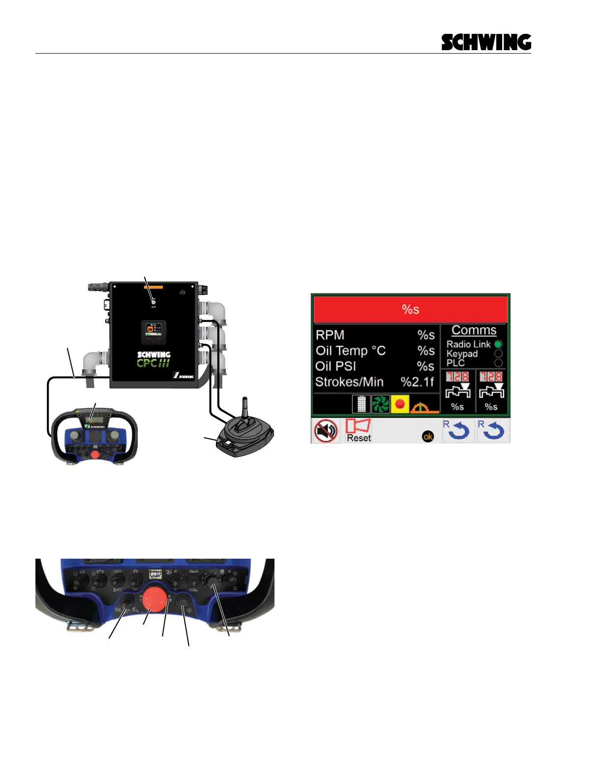
2. Tether Transmitter to the Control Panel with the
provided Connection Cable (Figure 1).
3. Clear the E-stop, by pressing and then turning
counter-clockwise (Figure 2).
98465796-00
Panel Assembly:
Schematic:
98458772
98455320
Boom Harness
(PBC)
Radio A
(PRADA)
Front Harness
(PFC)
Rear Harness
(PRC)
Programming Port
(PPPT)
I/O Harness
(PIOE)
Oil Temperature
(POTS)
Power
(PPG)
Pairing Port
Maintenance Switch
(PMS)
Radio C
(PRADC)
OFF
ON
In Maintenance mode, all CPC
safety features will be disabled
WARNING
DRIVE
DRIVE PUMP
33.5
PTO Hours
Aux
EF1/2
Connection Cable
Transmitter
Receiver
Figure 1
Tether Transmitter to Control Panel
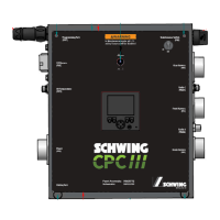
4. Make sure all Transmitter switches are either in
the “o” or “neutral” position. Stroke Limiter Dial
must be turned to “1” (Figure 2).
E-Stop
Power Button
Power LED
Stroke Limiter
Snail / Rabbit Switch
Figure 2
Transmitter switches and buttons
5. Switch o /on the receiver by unplugging Cable A
connector on the CPC III controller and then plug
back in.
6. Within 45 seconds press and hold the power but-
ton on the Transmitter for approximately 10 sec-
onds until the power LED (right of the E-Stop)
illuminates solid RED.
7. Release Power button and wait until the buzzer
produces 5 beeps in quick succession and the
transmitter is switched o automatically.
If the radio has be successfully paired, a green indicator
will appear next to the Radio Link under the Comms
column on the homepage screen.