3
Operation
CPC III Manual
Installation Instructions
These instructions will vary depending on the type of
unit you are replacing. They are general guidelines and
some system understanding will be needed to install
the CPC III. All of these steps need to be performed
with the vehicle shut-o.
Electrical Schematic: 98455320
Control Panel
1. Find the primary C32/CPC/CPC2 control panel.
See Figure 1.
POWER
REAR CTR
UMB CTR
RADIO CTR
ID
LINK
ALARM
E-STOP
WHEN WELDING ANYWHERE ON UNIT
POWER CABLE MUST BE DISCONNECTED
L1357-01
Figure 1
Original CPC panel
2. Remove the primary control panel and bracket
that holds it to the shock mounts.
3. The CPC III Control Panel is pre-assembled.
Remove the faceplate and disconnect the local/
remote switch and display (Figure 2). Put the
faceplate to the side for later.
Faceplate
Disconnect
Figure 2
Unplug Local/Remote switch and display, remove
faceplate
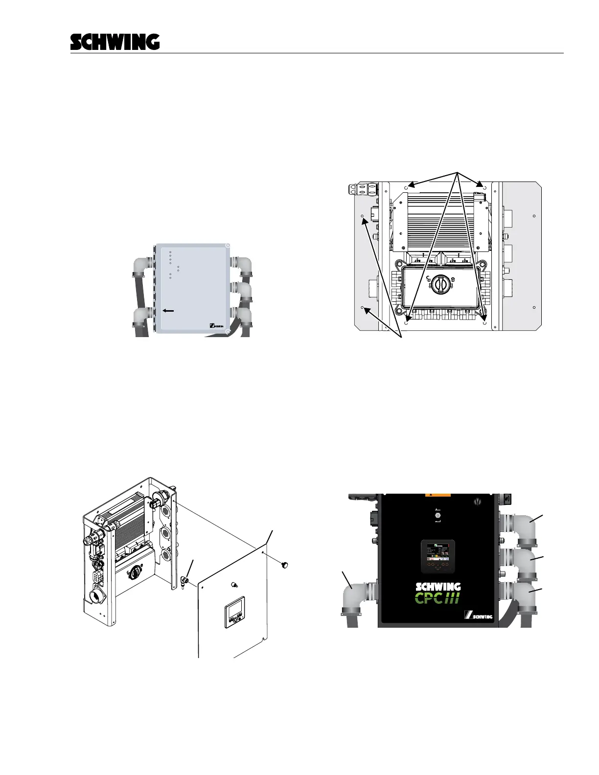
4. There are 4 holes provided to mount the CPC III
to the unit, two above the PLC and 2 below the
PDM. If your unit used the Mounting Plate and it
used the four holes on the far left and right, then
you may need to install the mounting panel to the
CPC III panel rst to match up the pattern.
Plate is only needed if the control
panel was mounted with these side holes.
Figure 3
Location of mounting holes
5. Install the CPC III Control Panel to the shock
mounts using the old hardware.
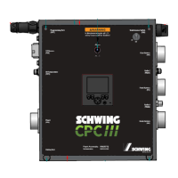
6. Connect the four cables that match the CPC III
control panel decal (PPC, PRC, PFC, PBC). The
old Radio connector is no longer needed and can
be removed.
PRC
PFC
PBC
PPG
98465796-00
Panel Assembly:
Schematic:
98458772
98455320
Boom Harness
(PBC)
Radio A
(PRADA)
Front Harness
(PFC)
Rear Harness
(PRC)
(PPPT)
I/O Harness
(PIOE)
Oil Temperature
(POTS)
Power
(PPC)
Pairing Port
(PMS)
Radio C
(PRADC)
OFF
ON
In Maintenance mode, all CPC
safety features will be disabled
Figure 4
Install connected
7. Install the faceplate and connect the display and
Local/Remote Switch.