OM-610-1002-1 Operator’s Manual Rev 37
PDS-2010 SECTION 5 OPERATION page 19
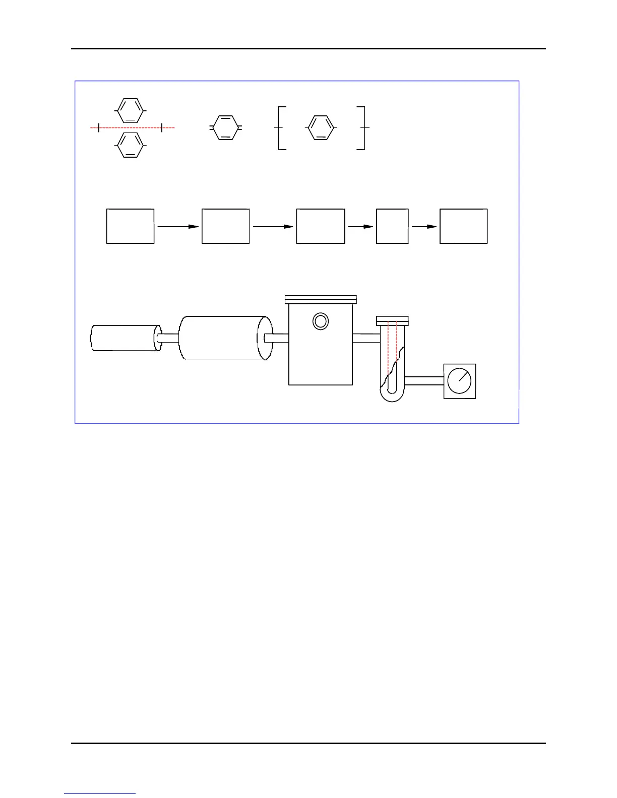
Figure 4: Parylene Deposition Process
CH
2
Di-para-xylylene
(Dimer)
Para-xylylene
(Monomer)
Poly-(para-xylylene)
(Polymer)
0.001 Torr
VAPORIZE
PYROLYZE
POLYMERIZE
DEPOSIT
Vaporizer Pyrolysis
Furnace
Deposition
Chamber
Cold Trap
Vacuum Pump
n
CH
2
CH
2
CH
2
CH
2
CH
2
CH
2
CH
2
-90° C
25° C
0.05 Torr
690° C
0.5 Torr
150° C
0.1 Torr
The Parylene coating system is a sealed system consisting of tubes and chambers that allow gas to flow from
the vaporizer section, through the pyrolysis zone, into the deposition chamber, past the probe cold trap, and
then through the vacuum pump (which exhausts to the atmosphere).
5.3.2.4 Typical Coating Cycle
1. The substrate to be coated is loaded in the deposition cham
ber and the chamber is sealed.
2. Parylene in its dimer form (similar in appearance to white laundry detergent) is loaded into the
ambient temperature vaporizer zone through the load door. The door is then sealed. The amount
of dimer loaded is dependent upon the required coating thickness, total surface area of substrate,
and deposition chamber size.
3. The sealed system is pumped down by the vacuum pump to a steady state pressure of 1-100
milliTorr, as indicated by a vacuum sensor connected to the deposition chamber. This is the base
pressure as described in Section 5.10.
 Loading...