Principle of coupling when stopped
- all the generating set power units are switched off,
- starting of all the generating sets,
- when the speed reaches 1450 rpm, activated excitation command on all the generating sets,
- the voltage generated by each generating set increases gradually and the voltage is therefore the same in all
generating sets,
- the generating sets therefore reach 1500 rpm at 400 V 50 Hz.
At the end of global operation, if the power consumed by the installation does not require the operation of all the
generating sets within the power plant, one or more generating sets will be stopped according to the wattmetric control.
Restarting of the generating set (these generating sets) depends on the load and wattmetric control of the load.
However, if a generating set is reconnected to a busbar already subjected to a load, the “recoupling” is carried out in
normal operation and not when the generating set is stopped.
Principle of coupling in normal operation
Coupling in normal operation enables all the generating sets to be coupled (in voltage and frequency) to a busbar supplied
by a generating set designed as master at the output.
A number (1 to 15) is assigned to each Kerys. This number serves solely to establish the IP address of each Kerys for
communication by Ethernet and loading the programs.
A second number (from 1 to 15) is also assigned to each Kerys and defines the priority.
Example: let us assume a plant of 8 generating sets
Gen set 1 2 3 4 5 6 7 8
Priority 08 07 06 05 04 03 02 01
The numbers on the first line enable the IP address of each Kerys to be allocated. The numbers on the second line define
the priority.Therefore Kerys no. 8 with priority 01 is considered to be the master generating set and closes its flow first. The
other generating sets then synchronise one by one to the central busbar, transmitting the information on voltage, frequency
and phase difference to this busbar (see sketch).
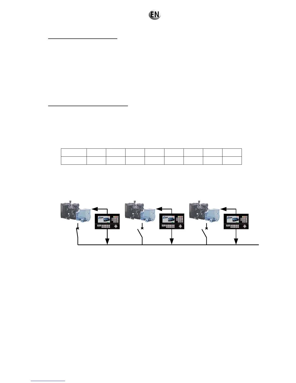
CB1
GS1
U1
CB2
GS2
U2
CB3
GS3
U3
Busbar U
Example for 3 GSs:
• DJ1 (Circuit breaker 1) is closed, the voltage is present on the busbar.
• Kerys 2 analyses the differences between U2 and U of the busbar before coupling.
• Kerys 3 analyses the differences between U3 and U of the busbar before coupling.
Each Kerys, independently of its neighbour, will close its discharge on the central busbar.