FORCED OPERATION
Start of FORCED OPERATION
• Generating set power units switched off.
• Generating set start request.
• The generating sets increase in speed.
• Speed stabilisation delay.
• Order of excitation for each generating set at nominal speed; the voltage is then quickly established on the busbar.
• Start of active power distribution.
• Resumption of application at rated voltage and frequency.
The Kerys PLCs remain in “AUTO” mode
The installation is supplied by the generating sets
End of FORCED OPERATION
• Generating set power units switched on.
• Cooling delay.
• Generating sets stopped and set to standby.
The Kerys PLCs remain in “AUTO” mode
The installation is supplied by the grid
Manual power plant operation
This mode of operation is selected with the “MANU” key. This enables the operator to start and stop the generating sets one by one
via the MMI keypad. The generating set power unit is switched off manually with synchronisation of each generating set to the
busbar using the MMI keys “+F”, “-F”, “+V” and “-V”. The distribution of power among the generating sets remains automatic. The
safety devices of the generating sets remain active in this mode of operation.
This mode of operation is the responsibility of the operator.
Without common part and without Normal/Emergency inverter (A633)
This configuration is designed to provide:
Emergency electricity supply to an installation following a grid loss (The grid loss is not controlled by the Kerys).
Return to
the grid can be achieved via Normal / Emergency switchover with a self-driven inverter (not controlled by the Kerys).
FORCED OPERATION with a generating set.
Operation in “Effacement Jour de Pointe” (EJP)* mode or other rates. (Information transmitted by dry contacts).
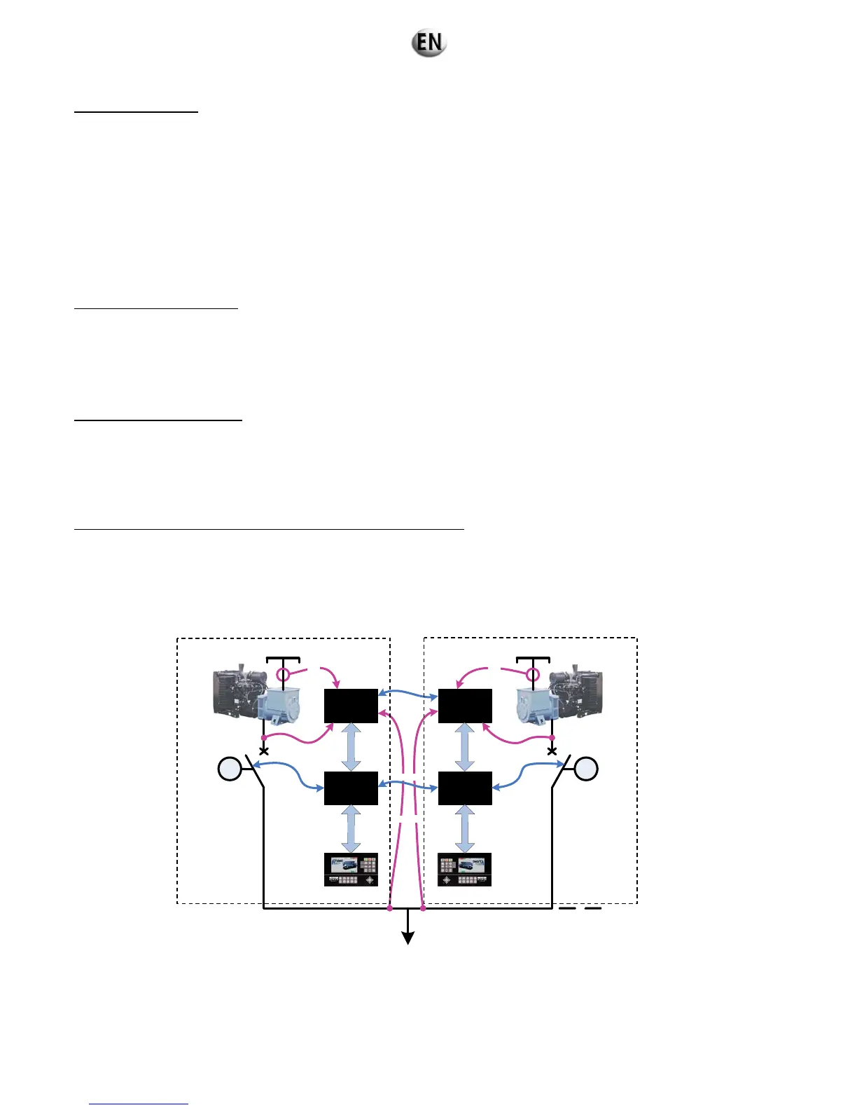
Active power regulation (speed of the generating sets) by digital buses connected between all the regulation modules.
Regulation
module
Base
module
C
A
N
b
u
s
E
t
h
e
r
n
e
t
3PH + N
3PH
M
3PH
3PH
Regulation
module
Base
module
C
A
N
b
u
s
E
t
h
e
r
n
e
t
3PH + N
M
3PH
Genset 1
Genset 2
Genset x
Digital Bus
Digital Bus
(*) the “EJP” system is specific to the French power grid.
Note 1: In this operating mode active and reactive power is distributed by a digital bus between the regulation modules (voltage of
the generating sets).
Note 2: In an installation of the power plant type (several generating sets connected by digital bus), two modes of coupling
between generating sets are possible
• Coupling when stopped.
• Coupling in normal operation.