35
Installation
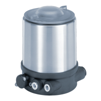
Type 024.16.720
Fastening
screws
max. 0.5 Nm
Fig. 20: Installing the positioner
Ensure that the pneumatic connections of the positioner and those of the valve actuator are situated
preferably vertically one above the other.
NOTE!
Too high torque when screwing in the fastening screw does not ensure protection class IP65 / IP67!
The fastening screws may be tightened to a maximum torque of 0.5 Nm only. •
→ Attach the positioner to the actuator using the two side fastening screws. In doing so, tighten the fas-
tening screws hand-tight only (maximum torque: 0.5 Nm).
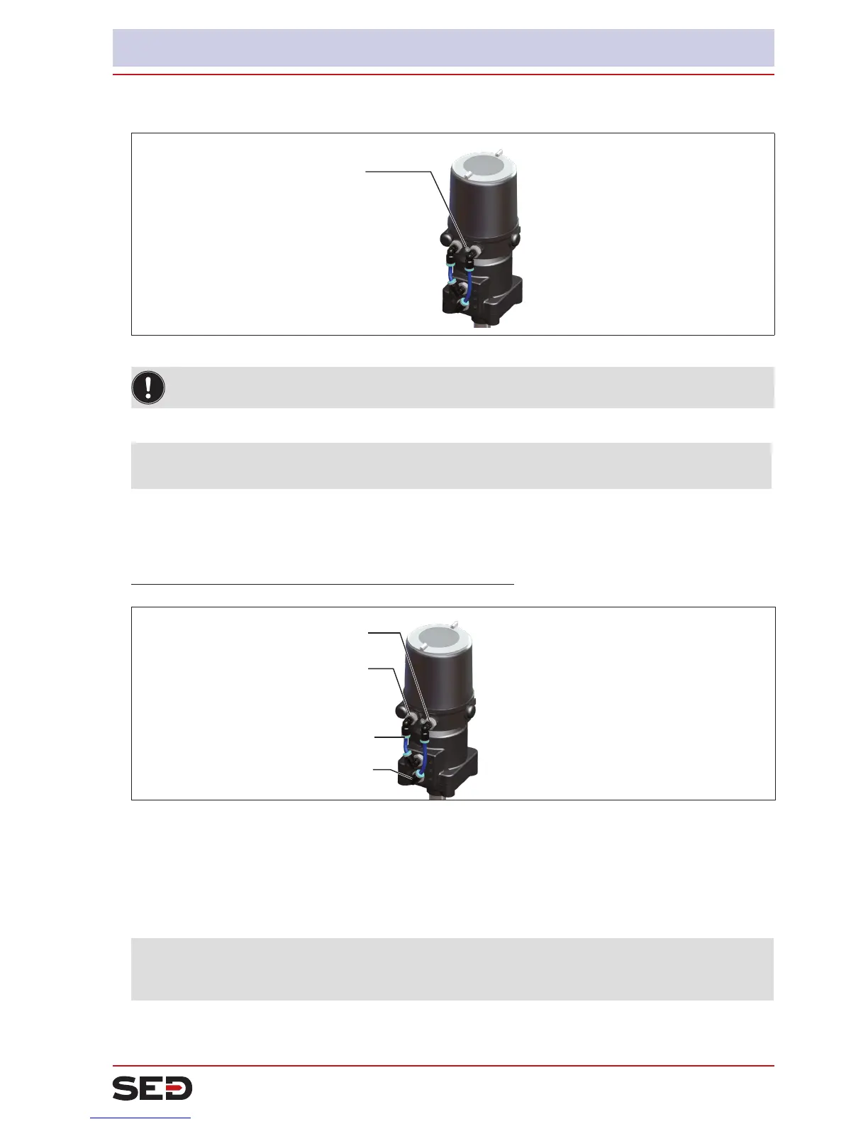
3. Install pneumatic connection between positioner and actuator
Control air connection 2
1
Control air connection 2
2
upper chamber
lower chamber
Fig. 21: Installing the positioner
→ Screw the plug-in hose connectors onto the positioner and the actuator.
→ Using the hoses supplied in the accessory kit, make the pneumatic connection between the positioner
and actuator with the following “Table 13: Pneumatic connection to actuator”.
NOTE!
Damage or malfunction due to ingress of dirt and moisture!
To comply with protection class IP65 / IP67, connect the control air connection which is not required to •
the free chamber of the actuator or seal with a plug.