Do you have a question about the Sega bop it ARCADE and is the answer not in the manual?
Information regarding product stickers and serial numbers.
Guidance on product warning displays and their importance for safety.
Constraints and guidelines for installing the product at the location.
Requirements for the physical space where the product will operate.
Checks and precautions to take before starting product operation.
Guidelines for monitoring and interacting with players during operation.
Identifies key components of the machine with numerical labels.
Lists and quantifies the accessories provided with the product.
Step-by-step guide on how to unpack the main cabinet.
Instructions for installing the main display unit onto the cabinet.
Procedures for mounting and connecting the billboard component.
Steps for securing the machine to the installation site and ensuring it is level.
Guidelines for safely connecting power and ground cables to the machine.
Tests to confirm proper assembly and connection of components.
Describes components that illuminate or activate when the machine is powered on.
Instructions for loading and replacing tickets in the ticket dispenser.
Safety guidelines and procedures for moving the machine.
Provides an overview of the game's objective, controls, and gameplay mechanics.
Describes the function of the switch unit and coin meter controls.
Details how to enter and use the game test mode for adjustments.
Parameters for adjusting game play, tickets, and difficulty.
Accessing and understanding game performance data and logs.
Instructions for clearing bookkeeping and IOU/Service meters.
Information on system hardware, software versions, and game name.
Procedures for testing the various lighting elements of the machine.
Procedures for testing the machine's LED and matrix displays.
Procedures for testing various input devices and controllers.
Procedures for testing output functions like ticket vending and meters.
Information on auxiliary CAN bus and COM port usage.
Configuration options for game audio volume, attract level, and language.
Instructions for setting the system's date and time.
How to exit test procedures and return to normal game operation.
Safety and handling guidelines for the controller units.
Step-by-step instructions for removing various control units from the machine.
Procedures for cleaning the coin selector to ensure proper coin acceptance.
Detailed steps for the mechanical cleaning of the coin selector.
Specific cleaning instructions for the SR3/NRI coin selector model.
Troubleshooting guide for common coin acceptor faults and their solutions.
Steps to adjust the price of play using the Excel Credit Board settings.
Table for setting coin acceptance and price of play based on country.
Quick reference for setting price of play for USA region using DIP switches.
Instructions for replacing the coin door lamp bulb.
A list detailing cabinet LEDs, their lighting part numbers, and quantities.
Diagrams showing the physical locations of cabinet LEDs.
Outlines a schedule for checking and maintaining machine components.
Guidelines for cleaning the machine's exterior surfaces safely.
Steps to resolve issues when no specific error message is displayed.
Safety guidelines for handling and installing the game board.
Procedures for locating and removing the game board unit.
An overview of the RED-2 game board's features and capabilities.
Detailed layout and identification of parts on the game board.
Identification and connection details for various connectors, switches, and LEDs on the game board.
Instructions for safely replacing the button battery on the game board.
Standard factory default settings for the game board DIP switches.
Refers to warning display stickers and their locations.
Hierarchical breakdown of major assemblies for the arcade unit.
Part list and diagram for the main arcade assembly.
Part list and diagram for the stabilizer back assembly.
Part list and diagram for the LCD display assembly.
Part list and diagram for the switch unit assembly.
Part list and diagram for the billboard assembly.
Part list and diagrams for the main cabinet assembly.
Part list and diagram for the AC unit assembly.
Part list and diagram for the left LED cluster assembly.
Part list and diagram for the right LED cluster assembly.
Part list and diagram for the control panel assembly.
Part list and diagram for the 'Pull It' controller assembly.
Part list and diagram for the shaft assembly of the 'Pull It' controller.
Part list and diagram for the 'Twist It' controller assembly.
Part list and diagram for the shaft assembly of the 'Twist It' controller.
Part list and diagram for the 'Flick It' controller assembly.
Part list and diagram for the shaft assembly of the 'Flick It' controller.
Part list and diagram for the 'Spin It' controller assembly.
Part list and diagram for the mould assembly of the 'Spin It' controller.
Part list and diagram for the 'Push It' controller assembly.
Part list and diagrams for the main display assembly.
Part list and diagram for the 'Bop It' control assembly.
Part list and diagram for the electrical enclosure assembly.
Part list and diagram for the bonus box assembly.
Part list and diagram for the main electrical board assembly.
Part list and diagram for the power supply unit assembly.
Part list and diagram for the installation kit assembly.
Explains the color coding convention for DC power wires used in diagrams.
Electrical schematic diagrams for the machine's components.
Electrical schematic diagrams for the machine's components.
Electrical schematic diagrams for the machine's components.
Contact details for SEGA parts and technical assistance.
Contact details for Play It Amusements for parts and support.
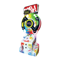
| Brand | Sega |
|---|---|
| Model | bop it ARCADE |
| Category | Arcade Game Machines |
| Language | English |