9
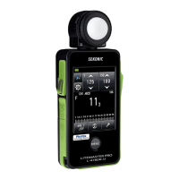
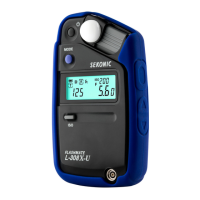
3.1.3 Removal of JR11-901(JR20-901) PCB /1 Assembly
a) Detach all of the lead wires soldered to the round of JR10-901(JR20-901) PCB/1 Assembly using the
soldering iron. Refer to the diagram below for the wiring. (JR109001 Wire Harness/1, JR109002
Wire Harness /2,JC109011 Wire Harness /K,JC109012 Wire Harness /L, JC109013 Wire Harness
/M)
b) Remove screws.
Remove the LCD Holder Stay Assy.
* The screw tightening torque is to be 7~9c*N*m(6.9~8.8kg*cm)
JR109001 Wire Harness /1(White)
JR109002 Wire Harness /2(Blue)
JC109011 Wire Harness /K(Brown)
JC109012 Wire Harness /L(Blue)
JC109013 Wire Harness /M(Red)
JR10-901
(JR20-901)
PCB/1
JR10-123
LCD Holder Stay Assy
ZA348(M1.7×6)
 Loading...