41
8. Error messages
There is a function for detecting circuit malfunctions and, in the conditions described below, switches
other than the power button are masked and error message is outputted to the LCD lower part.
[Error Display Example - ROM error]
Display Error Name Error Content Cause
Error10 : Firmware Error ROM error Error generated in ROM
sum-check
Firmware update failure
CPU damage
Error 9 : RAM Error RAM error Error generated in RAM check CPU damage
Error 7 : Timer Error Timer error Error generated in timer check CPU damage
Error 6 : A/D Error
A/D error A/D input standby is longer than
0.5 sec.
PCB (1) Assembly, PCB (2) Assembly
circuit damage
A/D count is greater than 65536 PCB (2) Assembly, PCB (3) Assembly
circuit damage
A/D count is 0 Poor connector contact between PCB
(1) and (2) Assembly
Flash input does not become
“H” (cordless)
Poor connector contact between PCB
(1) and (2) Assembly
Error 4 : Calibration Error Calibration
error
No calibration setting PCB (1) Assembly circuit damage
Error 3 : Backup Error Backup Error Backup Data sum check error PCB (1) Assembly circuit damage
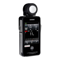
Error display section
 Loading...
