13
3.1.4 Removal of JR10-903 PCB / 3 Assembly and JR101210 Operation Button / 1
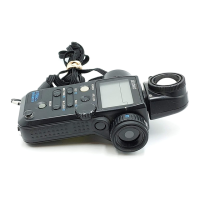
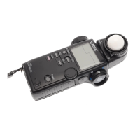
a) Remove the screw on PCB /3 Assembly. (ZA344:M1.7×4 4pcs.)
※The screw tightening torque is to be 7~9cNm(6.9~8.8kgcm)
b)The side of a Main Frame Cover / F Assembly(JR10-121 / JR20-121) is extended with a finger, the
portion of the nail of a PCB / 3 Assembly(JR10-903) of battery case is removed, and a PCB / 3
Assembly is removed.
c)A Operation Button / 1 (JR101210) are pushed and removed from the surface of a main part.
Cautions during assembly
・The screw tightening torque is to be 7~9cNm(6.9~8.8kgcm) (ZA344:M1.7×4 4pcs)
・When attaching a Operation Button / 1, the height of a Operation Button / 1 is united with the interval
of the rib of a Main Frame Cover / F Assembly .
The interval of the height of a Operation Button
1 and the rib of a Main Frame Cover / F
ssembly is united.
ZA344(M1.7×4)
4pcs
JR10-903
PCB / 3 Assembly
The nail of the battery case of a PCB / 3
Assembly is caught in a Main Frame Cover / F
(two places).
JR101210
Operation Button / 1
pushes
JR10-121(JR10-121)
Main Frame Cover / F Assembly
It extends with
finger.
JR10-903
PCB / 3 Assembly
The nail of the batter
case of a substrate/3
It extends with
finger.

 Loading...
